ENGINE UNIT REASSEMBLY

PROCEDURE
-
INSTALL CRANKSHAFT PULLEY SET KEY
-
Install the 2 pulley keys to the crankshaft.
-
-
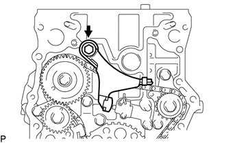
INSTALL NO. 4 CHAIN VIBRATION DAMPER
-
Install the vibration damper with the 2 bolts.
- Torque:
- 18 N*m { 184 kgf*cm, 13 ft.*lbf }
-
-
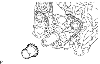
INSTALL NO. 2 CHAIN SUB-ASSEMBLY
-
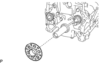
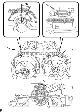
Install the timing sprocket as shown in the illustration.
Note
Check that the No. 1 cylinder is at TDC and that the weights of the No. 1 and No. 2 balanceshafts are at the bottom.
Tech Tips
Install the timing sprocket with the front mark facing forward.
-
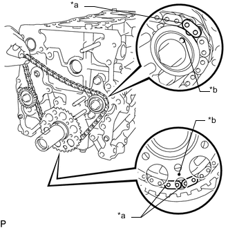
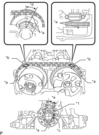
Text in Illustration *a Mark Plate (Yellow) *b Timing Mark As shown in the illustration, install the chain to the sprocket and gear with the mark plates aligned with the timing marks on the sprocket and gear.
-
Text in Illustration *a Mark Plate (Yellow) *b Large Timing Mark Fit the other mark link of the chain behind the large timing mark of the balanceshaft drive gear.
-
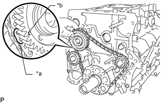
Insert the balanceshaft drive gear shaft through the balanceshaft drive gear so that it fits into the thrust plate hole.
-
Text in Illustration *a Large Timing Mark *b Small Timing Mark *c Mark Plate (Yellow) Align the small timing mark of the balanceshaft drive gear with the large timing mark of the balanceshaft timing gear.
-
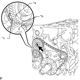
Install the bolt to the balanceshaft drive gear.
- Torque:
- 25 N*m { 255 kgf*cm, 18 ft.*lbf }
-
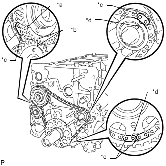
Text in Illustration *a Large Timing Mark *b Small Timing Mark *c Mark Plate (Yellow) *d Timing Mark Check that each timing mark is aligned with the corresponding mark link.
Note
Check that the No. 1 cylinder is at TDC and that the weights of the No. 1 and No. 2 balanceshafts are at the bottom.
-
-
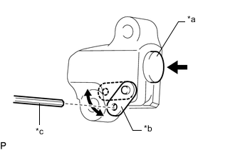
INSTALL NO. 2 CHAIN TENSIONER ASSEMBLY
-
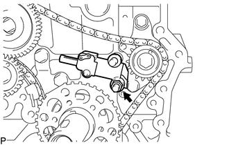
Install the chain tensioner assembly with the nut.
- Torque:
- 18 N*m { 184 kgf*cm, 13 ft.*lbf }
Note
Install the chain tensioner with the pin installed, and then remove the pin after installation. When performing this step, do not push the vibration damper against the chain.
-
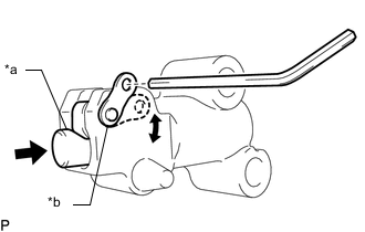
Text in Illustration *a Plunger *b Stopper Plate Move the stopper plate downward to release the lock and push the plunger deep into the tensioner.
-
Move the stopper plate upward to set the lock and insert a hexagon wrench into the stopper plate hole.
-
-
INSTALL NO. 3 CHAIN VIBRATION DAMPER
-
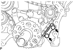
Install the chain vibration damper with the 2 bolts.
- Torque:
- 18 N*m { 184 kgf*cm, 13 ft.*lbf }
-
-
INSTALL NO. 2 CHAIN VIBRATION DAMPER
-
Install the chain vibration damper with the bolt.
- Torque:
- 27 N*m { 270 kgf*cm, 20 ft.*lbf }
-
-
INSTALL OIL CONTROL VALVE FILTER
-
Check that no foreign matter is on the mesh part of the filter.
If foreign matter is present, clean the part thoroughly.
-
Using an 8 mm hexagon wrench, install a new gasket and the oil control valve filter with the screw plug.
- Torque:
- 30 N*m { 306 kgf*cm, 22 ft.*lbf }
-
-
INSTALL CYLINDER HEAD GASKET
-
INSTALL CYLINDER HEAD SUB-ASSEMBLY
-
INSTALL CAMSHAFT TIMING EXHAUST GEAR ASSEMBLY
-
INSTALL CAMSHAFT TIMING GEAR ASSEMBLY
-
INSTALL VALVE STEM CAP
-
INSTALL VALVE LASH ADJUSTER ASSEMBLY
-
INSTALL NO. 1 VALVE ROCKER ARM SUB-ASSEMBLY
-
INSTALL CAMSHAFT
-
INSTALL CAMSHAFT BEARING CAP
-
INSTALL CRANKSHAFT TIMING GEAR OR SPROCKET
-
Install the crankshaft timing gear or sprocket as shown in the illustration.
-
-
INSTALL NO. 1 CHAIN VIBRATION DAMPER
-
Install the No. 1 chain vibration damper with the bolt and nut.
- Torque:
- for bolt
- 21 N*m { 214 kgf*cm, 15 ft.*lbf }
- for nut
- 18 N*m { 184 kgf*cm, 13 ft.*lbf }
-
Remove the hexagon wrench from the No. 2 chain tensioner assembly and release the plunger.
-
-
INSTALL CHAIN SUB-ASSEMBLY
-
Text in Illustration *1 Crankshaft Pulley Set Key *a Timing Mark *b Mark Plate (Pink) *c Mark Plate (Yellow) *d Approximately 13° *e Approximately 30° As shown in the illustration, install the chain sub-assembly to the camshaft timing exhaust gear assembly and camshaft timing gear assembly with the mark plates aligned with the timing marks on the camshaft timing exhaust gear assembly and camshaft timing gear assembly.
Tech Tips
-
The camshaft mark plate is pink.
-
The crankshaft mark plate is yellow.
-
-
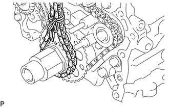
Use a rope to tie the chain sub-assembly of the crankshaft timing gear or sprocket. Tie the rope near the crankshaft timing gear or sprocket.
Note
After the chain tensioner has been installed, the rope must be removed.
Tech Tips
The rope is tied so that the chain sub-assembly will not jump a tooth.
-
-
INSTALL CHAIN TENSIONER SLIPPER
-
Install the chain tensioner slipper with the bolt.
- Torque:
- 21 N*m { 214 kgf*cm, 15 ft.*lbf }
-
-
INSTALL NO. 1 CHAIN TENSIONER ASSEMBLY
-
Text in Illustration *a Plunger *b Stopper Plate *c Hexagon Wrench Move the stopper plate upward to release the lock and push the plunger deep into the tensioner.
-
Move the stopper plate downward to set the lock and insert a hexagon wrench into the hole of the stopper plate.
-
Install a new gasket and the No. 1 chain tensioner assembly with the bolt and nut.
- Torque:
- 10 N*m { 102 kgf*cm, 7 ft.*lbf }
-
Remove the hexagon wrench from the No. 1 chain tensioner assembly and release the plunger.
-
-
CHECK NO. 1 CYLINDER TO TDC/COMPRESSION
-
Text in Illustration *1 Crankshaft Pulley Set Key *a Timing Mark *b Approximately 13° *c Approximately 30° Check that the No. 1 cylinder is set to TDC/compression.
-
Rotate the crankshaft two full rotations, and then check that all timing marks are in the position shown in the illustration.
If the timing marks do not match, set the chain sub-assembly again.
-
-
-
INSTALL TIMING CHAIN GUIDE
-
Install a new O-ring to the No. 1 camshaft bearing cap.
-
Install the timing chain guide with the 2 bolts.
- Torque:
- 10 N*m { 102 kgf*cm, 7 ft.*lbf }
-
-
INSTALL CYLINDER HEAD COVER CONNECTOR SUB-ASSEMBLY
-
Install a new No. 2 camshaft bearing cap oil hole gasket and 3 new No. 3 camshaft bearing cap oil hole gaskets to the No. 1 camshaft bearing cap.
-
Install the cylinder head cover connector sub-assembly with the 2 bolts.
- Torque:
- 10 N*m { 102 kgf*cm, 7 ft.*lbf }
-
-
INSTALL ENGINE WATER PUMP ASSEMBLY
-
INSTALL TIMING CHAIN COVER SUB-ASSEMBLY
-
INSTALL V-RIBBED BELT TENSIONER ASSEMBLY
-
INSTALL TIMING CHAIN COVER OIL SEAL
-
INSTALL NO. 1 TAPER SCREW PLUG (w/o Oil Cooler)
-
Install the No. 1 taper screw plug to the cylinder block.
- Torque:
- 25 N*m { 250 kgf*cm, 18 ft.*lbf }
-
-
INSTALL UNION (w/ Oil Cooler)
-
Install the union to the cylinder block.
- Torque:
- 25 N*m { 250 kgf*cm, 18 ft.*lbf }
-
-
INSTALL OIL FILTER BRACKET SUB-ASSEMBLY
-
Using a hexagon wrench, install the oil filter bracket union.
- Torque:
- 25 N*m { 250 kgf*cm, 18 ft.*lbf }
-
Install a new oil filter bracket gasket to the oil filter bracket.
-
Install a new O-ring to the oil filter bracket union.
Note
Apply a light coat of engine oil to the O-ring and oil filter bracket.
-
Install 2 new gaskets and the 2 screw plugs to the oil filter bracket.
- Torque:
- 49 N*m { 500 kgf*cm, 36 ft.*lbf }
-
Install the oil filter bracket with the 2 bolts and nut.
- Torque:
- 25 N*m { 255 kgf*cm, 18 ft.*lbf }
-
-
INSTALL OIL FILTER UNION (w/o Oil Cooler)
-
Using a 27 mm socket wrench, install the oil filter union.
- Torque:
- 43 N*m { 439 kgf*cm, 32 ft.*lbf }
-
-
INSTALL OIL COOLER ASSEMBLY (w/ Oil Cooler)
-
INSTALL NO. 4 WATER BY-PASS PIPE (w/ Oil Cooler)
-
Install the No. 4 water by-pass pipe with the 2 bolts.
- Torque:
- 20 N*m { 204 kgf*cm, 15 ft.*lbf }
-
Connect the No. 5 water by-pass hose to the oil cooler assembly, and slide the clip to secure the hose.
-
-
INSTALL NO. 4 WATER BY-PASS HOSE (w/ Oil Cooler)
-
Install the No. 4 water by-pass hose to the oil cooler assembly and union, and slide the clips to secure the hoses.
-
-
INSTALL OIL FILTER SUB-ASSEMBLY
-
INSTALL ENGINE COOLANT TEMPERATURE SENSOR
-
INSTALL KNOCK SENSOR
-
INSTALL ENGINE OIL PRESSURE SWITCH ASSEMBLY
-
INSTALL REAR ENGINE OIL SEAL RETAINER
-
Clean and degrease the contact surfaces of the rear engine oil seal retainer and cylinder block sub-assembly.
-
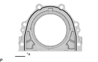
Text in Illustration *a Seal Packing Apply seal packing in a continuous bead as shown in the illustration.
Seal packing Toyota Genuine Seal Packing Black, Three Bond 1207B or equivalent Standard seal diameter 2.0 to 3.0 mm (0.0787 to 0.118 in.) Note
-
Remove any oil from the contact surface.
-
Install the rear engine oil seal retainer within 3 minutes after applying seal packing.
-
Do not start the engine for at least 4 hours after installation.
-
-
Install the rear engine oil seal retainer with the 6 bolts.
- Torque:
- 13 N*m { 133 kgf*cm, 10 ft.*lbf }
-
-
INSTALL REAR ENGINE OIL SEAL
-
INSTALL OIL PAN STUD BOLT
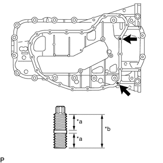
Text in Illustration *a 9.0 mm (0.354 in.) *b 19.0 mm (0.748 in.) Note
If a stud bolt is deformed or threads are damaged, replace it.
-
Using E6 "TORX" socket wrench, install the stud bolts.
- Torque:
- 3.0 N*m { 31 kgf*cm, 27 in.*lbf }
-
-
INSTALL OIL STRAINER SUB-ASSEMBLY
-
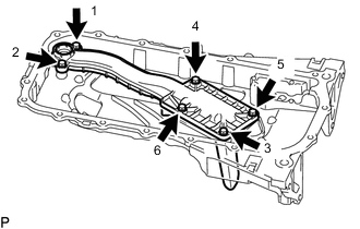
Install the oil strainer sub-assembly with the 6 bolts, and tighten the 6 bolts in the sequence shown in the illustration.
- Torque:
- 10 N*m { 102 kgf*cm, 7 ft.*lbf }
-
Install a new gasket to the oil strainer sub-assembly.
-
-
INSTALL OIL PAN SUB-ASSEMBLY
-
INSTALL NO. 2 OIL PAN SUB-ASSEMBLY
-
INSTALL OIL PAN COVER SILENCER
-
INSTALL CRANKSHAFT PULLEY
-
INSTALL THERMOSTAT
-
INSTALL WATER INLET
-
INSTALL NO. 1 VENTILATION CONNECTOR
-
INSTALL CYLINDER HEAD COVER SUB-ASSEMBLY
-
INSTALL CAMSHAFT TIMING OIL CONTROL VALVE ASSEMBLY (for Exhaust Side)
-
INSTALL CAMSHAFT TIMING OIL CONTROL VALVE ASSEMBLY (for Intake Side)
-
INSTALL CRANKSHAFT POSITION SENSOR
-
INSTALL CAMSHAFT POSITION SENSOR (for Exhaust Side)
-
INSTALL CAMSHAFT POSITION SENSOR (for Intake Side)
-
INSTALL PCV VALVE SUB-ASSEMBLY
-
INSTALL OIL FILLER CAP SUB-ASSEMBLY
-
Install the gasket to the oil filler cap.
-
Install the oil filler cap.
-
-
INSTALL SPARK PLUG