ENGINE UNIT REASSEMBLY

PROCEDURE
-
INSTALL STRAIGHT PIN
Note
It is not necessary to remove the straight pin unless it is being replaced.
-
for Timing Chain Cover Sub-assembly Side:
-
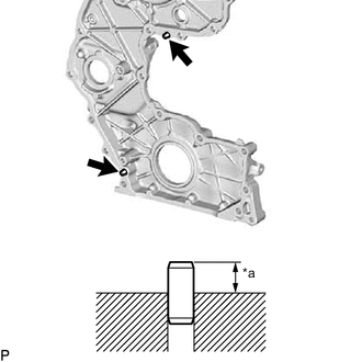
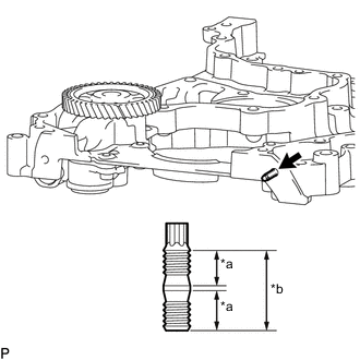
Text in Illustration *a Protrusion Height Using a plastic-faced hammer, tap in 2 new straight pins to the timing chain cover sub-assembly.
Standard protrusion height 5.0 to 7.0 mm (0.197 to 0.276 in.)
-
-
for Timing Chain Case Assembly Side:
-
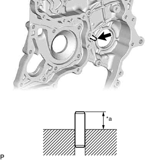
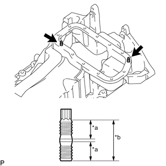
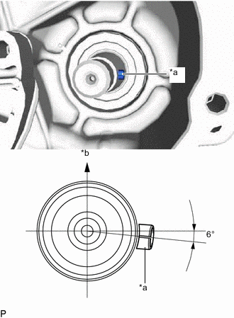
Text in Illustration *a Protrusion Height Using a plastic-faced hammer, tap in a new straight pin to the timing chain case assembly.
Standard protrusion height 18 to 20 mm (0.709 to 0.787 in.)
-
-
-
INSTALL STUD BOLT
Note
If a stud bolt is deformed or its threads are damaged, replace it.
-
for Timing Chain Cover Sub-assembly Side:
-
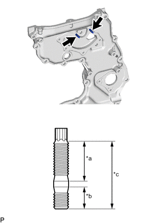
Text in Illustration *a 16 mm (0.630 in.) *b 9.0 mm (0.354 in.) *c 27 mm (1.06 in.) Using an E6 "TORX" socket wrench, install the stud bolts to the timing chain cover sub-assembly.
- Torque:
- 6.0 N*m { 61 kgf*cm, 53 in.*lbf }
-
-
for Timing Chain Case Assembly Side:
-
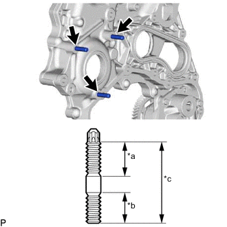
Text in Illustration *a 19 mm (0.748 in.) *b 16 mm (0.630 in.) *c 44 mm (1.73 in.) Using an E8 "TORX" socket wrench, install the stud bolts to the timing chain case assembly.
- Torque:
- 10 N*m { 102 kgf*cm, 7 ft.*lbf }
-
-
Text in Illustration *a 9.0 mm (0.354 in.) *b 19 mm (0.748 in.) Using an E6 "TORX" socket wrench, install the stud bolt to the timing chain case assembly.
- Torque:
- 6.0 N*m { 61 kgf*cm, 53 in.*lbf }
-
for Oil Pan Sub-assembly Side:
-
Text in Illustration *a 9.0 mm (0.354 in.) *b 19 mm (0.748 in.) Using an E6 "TORX" socket wrench, install the 2 stud bolts to the oil pan sub-assembly.
- Torque:
- 6.0 N*m { 61 kgf*cm, 53 in.*lbf }
-
-
-
INSTALL LOCK PLATE
-
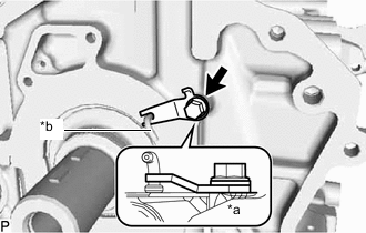
Text in Illustration *a Cylinder Block Sub-assembly Side *b Oil Jet Install the lock plate to the cylinder block sub-assembly with the bolt.
- Torque:
- 10 N*m { 102 kgf*cm, 7 ft.*lbf }
Tech Tips
-
Make sure the lock plate is facing the direction shown in the illustration.
-
Make sure the end of the lock plate is holding the oil jet as shown in the illustration.
-
-
INSTALL CYLINDER HEAD GASKET
-
INSTALL CYLINDER HEAD SUB-ASSEMBLY
-
INSTALL VALVE LASH ADJUSTER ASSEMBLY
-
Install the 16 valve lash adjuster assemblies to the cylinder head sub-assembly.
-
-
INSTALL NO. 1 VALVE ROCKER ARM SUB-ASSEMBLY
-

Text in Illustration *1 No. 1 Valve Rocker Arm Sub-assembly *2 Valve Stem Cap *3 Valve Lash adjuster assembly Check that the No. 1 valve rocker arm sub-assembly is firmly set to the valve lash adjuster assembly.
-
Apply a light coat of engine oil to the camshaft journals of the cylinder head sub-assembly and the thrust portion of the camshaft.
-
Install the 16 No. 1 valve rocker arm sub-assemblies to the 16 valve lash adjuster assemblies.
-
-
INSTALL NO. 2 CAMSHAFT
Tech Tips
The glove is at the rear end of the No. 2 camshaft.
Text in Illustration *a Glove 
Engine Front Side
-
Clean the No. 2 camshaft journals.
-
Apply a light coat of engine oil to the No. 2 camshaft journals of the cylinder head sub-assembly and the thrust portion of the No. 2 camshaft.
-
-
INSTALL CAMSHAFT
-
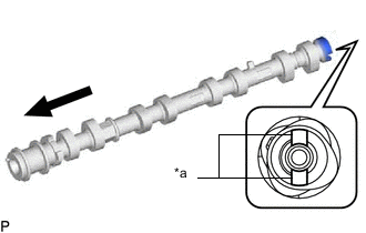
Clean the camshaft journals.
-
Apply a light coat of engine oil to the camshaft journals of the cylinder head sub-assembly and the thrust portion of the camshaft.
-

Text in Illustration *a Knock Pin Make sure the knock pins of the camshaft and No. 2 camshaft are facing the direction shown in the illustration.
-
-
INSTALL NO. 1 AND NO. 2 CAMSHAFT BEARING CAP
-

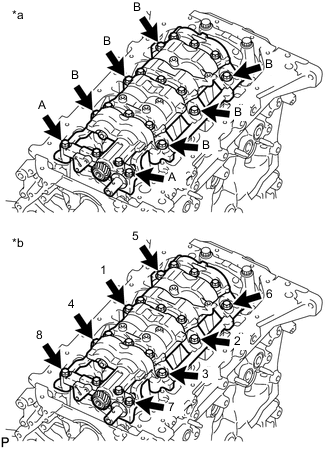
Set the No. 1 camshaft bearing cap and 8 No. 2 camshaft bearing caps to the cylinder head sub-assembly as shown in the illustration.
-
Temporarily install the 20 camshaft bearing cap bolts.
-
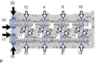
Uniformly tighten the 20 camshaft bearing cap bolts in several steps in the order shown in the illustration.
- Torque:
- for camshaft bearing cap bolt A (No. 1 camshaft bearing)
- 21 N*m { 214 kgf*cm, 15 ft.*lbf }
- for camshaft bearing cap bolt B (No. 2 camshaft bearing)
- 10 N*m { 102 kgf*cm, 7 ft.*lbf }
Text in Illustration Camshaft Bearing Cap Bolt A 
Camshaft Bearing Cap Bolt B
-
-
INSTALL NO. 3 CAMSHAFT BEARING CAP
-
Clean and degrease the contact surfaces of the No. 3 camshaft bearing cap and cylinder head sub-assembly.
-
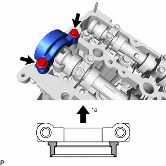
Text in Illustration *a Engine Front Side 
Seal Packing Application Area Apply seal packing to the No. 3 camshaft bearing cap in the areas indicated in the illustration.
Seal packing Toyota Genuine Seal Packing Black, Three Bond 1207B or equivalent Standard seal diameter 3.0 mm (0.118 in.) Note
-
Install the No. 3 camshaft bearing cap within 3 minutes and tighten the camshaft bearing cap bolts within 15 minutes after applying seal packing.
-
Do not add engine oil within 2 hours of installation.
-
Do not start the engine for at least 2 hours after the installation.
-
-
Install the No. 3 camshaft bearing cap to the cylinder head sub-assembly with the 2 camshaft bearing cap bolts.
- Torque:
- 21 N*m { 214 kgf*cm, 15 ft.*lbf }
-
Wipe off excess seal packing from between No. 3 camshaft bearing cap and cylinder head sub-assembly.
-
-
INSTALL TIMING CHAIN CASE ASSEMBLY AND ENGINE WATER PUMP ASSEMBLY
-
INSTALL INJECTION PUMP INSULATOR
-
Install the injection pump insulator to the cylinder block sub-assembly.
-
-
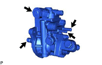
INSTALL SUPPLY PUMP ASSEMBLY
Note
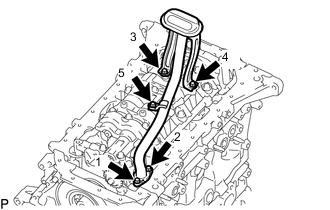
Do not hold the supply pump assembly by the parts indicated by the arrows in the illustration.
-
Install a new O-ring to the supply pump assembly.
-
Install the supply pump assembly to the timing chain case assembly with the 3 nuts.
- Torque:
- 21 N*m { 214 kgf*cm, 15 ft.*lbf }
-
Install the No. 1 fuel pump bracket to the cylinder block sub-assembly and supply pump assembly with the 2 bolts.
- Torque:
- 21 N*m { 214 kgf*cm, 15 ft.*lbf }
-
-
INSTALL NO. 1 CHAIN TENSIONER SLIPPER
-
Install the No. 1 chain tensioner slipper to the straight pin.
-
-
TEMPORARILY INSTALL NO. 1 CHAIN VIBRATION DAMPER
-
Temporarily install the No. 1 chain vibration damper to the cylinder block sub-assembly with the bolt.
-
-
INSTALL CRANKSHAFT TIMING SPROCKET, INJECTION PUMP DRIVE GEAR WITH NO. 1 CHAIN SUB-ASSEMBLY
-
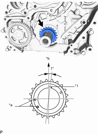
Text in Illustration *1 Crankshaft Pulley Set Key *a Timing Mark *b Upper Side Install the crankshaft timing sprocket to the crankshaft.
-
Align the crankshaft pulley set key as shown in the illustration.
-
Text in Illustration *a Supply Pump Shaft Key *b Upper Side Align the supply pump shaft key as shown in the illustration.
-
Remove the crankshaft timing sprocket from the crankshaft.
-
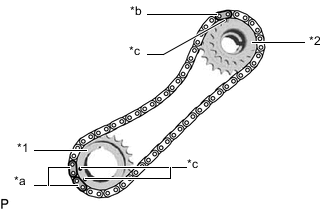
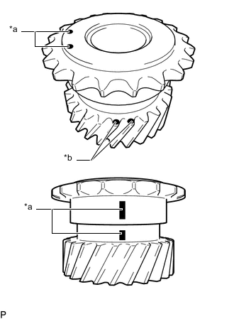
Text in Illustration *1 Crankshaft Timing Sprocket *2 Injection Pump Drive Gear *a Mark Plate (Pink) *b Mark Plate (Yellow) *c Timing Mark Align the 2 mark plates (pink) of the No. 1 chain sub-assembly with the 2 timing marks of the crankshaft timing sprocket and install the No. 1 chain sub-assembly to the crankshaft timing sprocket as shown in the illustration.
-
Align the mark plate (yellow) of the No. 1 chain sub-assembly with the timing mark of the injection pump drive gear and install the No. 1 chain sub-assembly to the injection pump drive gear as shown in the illustration.
-
Install the crankshaft timing sprocket, injection pump drive gear and No. 1 chain sub-assembly to the crankshaft and supply pump shaft together.
-
-
TIGHTEN NO. 1 CHAIN VIBRATION DAMPER
-
Tighten the No. 1 chain vibration damper to the cylinder block sub-assembly with the bolt.
- Torque:
- 21 N*m { 214 kgf*cm, 15 ft.*lbf }
-
-
INSTALL NO. 1 CHAIN TENSIONER ASSEMBLY
Note
-
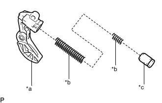
When the pin is removed from the No. 1 chain tensioner assembly, the plunger and spring may come off of the No. 1 chain tensioner assembly body, but this is not a malfunction.
-
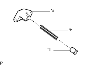
Before installing the plunger and spring to the No. 1 chain tensioner assembly body, check that they are free of foreign matter and not damaged.
Text in Illustration *a No. 1 Chain Tensioner Assembly Body *b Spring *c Plunger
-
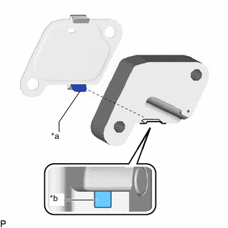
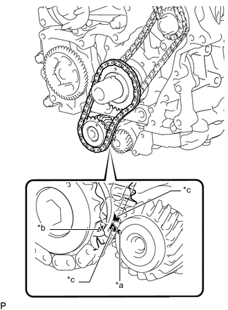
Text in Illustration *a Claw (Lower Side) *b Groove Install a new gasket and No. 1 chain tensioner assembly to the cylinder block sub-assembly with the 2 bolts.
- Torque:
- 10 N*m { 102 kgf*cm, 7 ft.*lbf }
Tech Tips
Align the claw (lower side) of the gasket with the groove of the No. 1 chain tensioner assembly body to install the No. 1 chain tensioner assembly as shown in the illustration.
-
-
INSTALL SUPPLY PUMP SHAFT NUT
-
Temporarily install the crankshaft pulley and crankshaft pulley set bolt to the crankshaft.
-
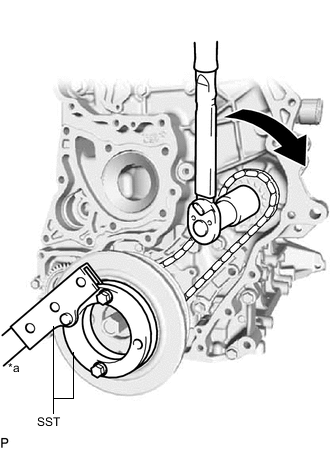
Text in Illustration *a Hold Turn Using SST, hold the crankshaft pulley and install the supply pump shaft nut to the supply pump shaft.
- SST
- 09213-58014 ( 91551-80840 )
- 09330-00021
- Torque:
- 137 N*m { 1397 kgf*cm, 101 ft.*lbf }
Note
If the supply pump shaft nut is tightened with torque higher than the specified torque, the No. 1 chain sub-assembly may break.
-
Remove the crankshaft pulley set bolt and crankshaft pulley from the crankshaft.
-
Text in Illustration *1 Crankshaft Timing Sprocket *2 Injection Pump Drive Gear *a Mark Plate (Pink) *b Mark Plate (Yellow) *c Timing Mark Make sure that the timing marks of the crankshaft timing sprocket and injection pump drive gear are aligned with the mark plates of the No. 1 chain sub-assembly as shown in the illustration.
-
Remove the pin from the No. 1 chain tensioner assembly.
-
-
INSTALL CAMSHAFT TIMING SPROCKET
-
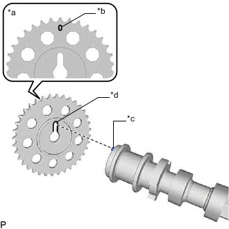
Text in Illustration *a Engine Front Side *b Timing Mark *c Knock Pin *d Cutout Temporarily install the 2 camshaft timing sprockets to the camshaft and No. 2 camshaft with the 2 camshaft timing sprocket bolts.
Note
Make sure that the timing mark of the camshaft timing sprocket faces the front side of the engine.
Tech Tips
Align the knock pins of the camshaft and No. 2 camshaft with the cutout of the camshaft timing sprocket to install the camshaft timing sprocket.
-
for Intake Side:
-
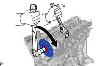
Text in Illustration *a Hold Turn Using a wrench to hold the hexagonal portion of the camshaft, install the camshaft timing sprocket bolt to the camshaft.
- Torque:
- 81 N*m { 826 kgf*cm, 60 ft.*lbf }
Note
Be careful not to damage the camshaft or cylinder head sub-assembly with the wrench.
-
-
for Exhaust Side:
-
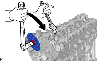
Text in Illustration *a Hold Turn Using a wrench to hold the hexagonal portion of the No. 2 camshaft, install the camshaft timing sprocket bolt to the No. 2 camshaft.
- Torque:
- 81 N*m { 826 kgf*cm, 60 ft.*lbf }
Note
Be careful not to damage the No. 2 camshaft or cylinder head sub-assembly with the wrench.
-
-
-
INSTALL NO. 2 CHAIN VIBRATION DAMPER
-
Install the No. 2 chain vibration damper to the timing chain case assembly with the 2 bolts.
- Torque:
- 21 N*m { 214 kgf*cm, 15 ft.*lbf }
-
-
INSTALL NO. 2 CHAIN SUB-ASSEMBLY
-
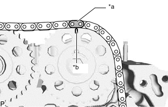
Text in Illustration *a Mark Plate (Orange) *b Timing Mark Align the mark plate (orange) of the No. 2 chain sub-assembly with the timing mark of the camshaft timing sprocket (intake side) and install the No. 2 chain sub-assembly to the camshaft timing sprocket (intake side) as shown in the illustration.
-
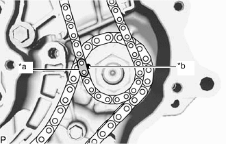
Text in Illustration *a Mark Plate (Yellow) *b Timing Mark Align the mark plate (yellow) of the No. 2 chain sub-assembly with the timing mark of the injection pump drive gear and install the No. 2 chain sub-assembly to the injection pump drive gear as shown in the illustration.
-
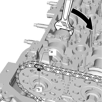
Text in Illustration *a Mark Plate (Orange) *a Timing Mark Turn Using a wrench, turn the hexagonal portion of the No. 2 camshaft clockwise and align the mark plate (orange) of the No. 2 chain sub-assembly with the timing mark of the camshaft timing sprocket (exhaust side) to install the No. 2 chain sub-assembly to the camshaft timing sprocket (exhaust side).
-
-
INSTALL NO. 2 CHAIN TENSIONER SLIPPER
-
Install the No. 2 chain tensioner slipper to the timing chain case assembly with the bolt.
- Torque:
- 21 N*m { 214 kgf*cm, 15 ft.*lbf }
-
-
INSTALL NO. 2 CHAIN TENSIONER ASSEMBLY
-
Install the No. 2 chain tensioner assembly to the timing chain case assembly with the 2 bolts.
- Torque:
- 10 N*m { 102 kgf*cm, 7 ft.*lbf }
-
Remove the pin from the No. 2 chain tensioner assembly.
-
-
INSTALL TIMING CHAIN GUIDE
-
CHECK NO. 1 CYLINDER TO TDC/COMPRESSION
-
Make sure that the timing marks of the camshaft timing sprocket (exhaust side), camshaft timing sprocket (intake side), injection pump drive gear and crankshaft timing sprocket are at the positions shown in the illustration.
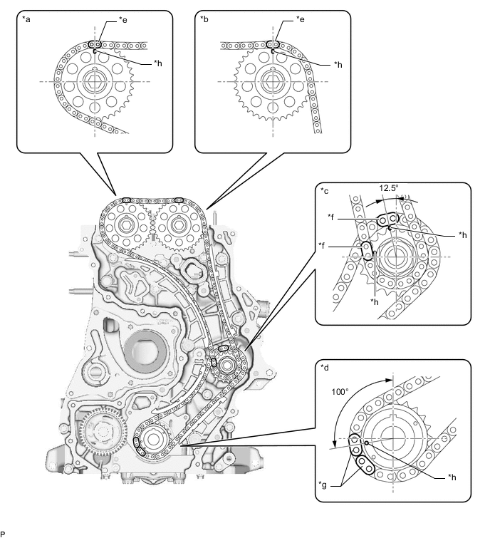
Text in Illustration *a Camshaft Timing Sprocket (Exhaust Side) *b Camshaft Timing Sprocket (Intake Side) *c Injection Pump Drive Gear *d Crankshaft Timing Sprocket *e Mark Plate (Orange) *f Mark Plate (Yellow) *g Mark Plate (Pink) *h Timing Mark
-
-
INSTALL ENGINE BALANCER ASSEMBLY
-
Set the engine balancer assembly to the cylinder block sub-assembly.
-
Text in Illustration *a Bolt Type *b Tightening Order Install the engine balancer assembly to the cylinder block sub-assembly with the 8 bolts and tighten the bolts in the sequence shown in the illustration.
- Torque:
- for bolt A
- 21 N*m { 214 kgf*cm, 15 ft.*lbf }
- for bolt B
- 43 N*m { 438 kgf*cm, 32 ft.*lbf }
Bolt Length Item Specified Condition Bolt A 50 mm (1.97 in.) Bolt B 55 mm (2.17 in.)
-
-
INSTALL BALANCE SHAFT TIMING SPROCKET, BALANCE SHAFT GEAR SUB-ASSEMBLY WITH NO. 3 CHAIN SUB-ASSEMBLY
Tech Tips
Before installing the balance shaft gear sub-assembly, make sure to confirm the positions of the timing marks and paint marks (pink).
-

Text in Illustration *a Timing Mark *b Paint Mark (Pink) Align the mark plate (yellow) of the No. 3 chain sub-assembly with the timing mark of the balance shaft timing sprocket and install the No. 3 chain sub-assembly to the balance shaft timing sprocket as shown in the illustration.
Note
Make sure that the timing plate of the No. 3 chain sub-assembly faces the front side of the engine.
-
Align the 2 mark plates (yellow) of the No. 3 chain sub-assembly with the 2 timing marks of the balance shaft timing gear sub-assembly and install the No. 3 chain sub-assembly to the balance shaft timing gear sub-assembly as shown in the illustration.
-
Text in Illustration *1 Balance Shaft Timing Sprocket *2 Balance Shaft Gear Sub-assembly *a Mark Plate (Yellow) *b Timing Mark Apply engine oil to the position shown in the illustration.
-
Text in Illustration *a Timing Mark (Engine Balancer Assembly Side) *b Timing Mark (Balance Shaft Gear Sub-assembly Side) *c Paint Mark (Pink)
(Balance Shaft Gear Sub-assembly Side)
Align the timing mark of the engine balancer assembly with the 2 paint marks (pink) and timing mark of the balance shaft gear sub-assembly, and then install the balance shaft timing sprocket, balance shaft gear sub-assembly with No. 3 chain sub-assembly to the crankshaft and engine balancer assembly as shown in the illustration.
-
Text in Illustration *1 Balance Shaft Timing Sprocket *2 Balance Shaft Gear Sub-assembly *a Mark Plate (Yellow) *b Timing Mark Make sure that the timing marks of the balance shaft timing sprocket and balance shaft gear sub-assembly are aligned with the mark plates of the No. 3 chain sub-assembly as shown in the illustration.
-
-
INSTALL NO. 1 BALANCE SHAFT THRUST PLATE
-
Apply engine oil to the front and rear surfaces of the No. 1 balance shaft thrust plate.
-
Install the No. 1 balance shaft thrust plate to the crankshaft with the bolt.
- Torque:
- 21 N*m { 214 kgf*cm, 15 ft.*lbf }
-
-
INSTALL NO. 3 CHAIN TENSIONER ASSEMBLY
Note
-
When the pin is removed from the No. 3 chain tensioner assembly, the plunger and 2 springs may come off of the No. 3 chain tensioner assembly body, but this is not a malfunction.
-
Before installing the plunger and 2 springs to the No. 3 chain tensioner assembly body, check that they are free of foreign matter and not damaged.
Text in Illustration *a No. 3 Chain Tensioner Assembly Body *b Spring *c Plunger
-
Install the No. 3 chain tensioner assembly to the engine balancer assembly with the 2 bolts.
- Torque:
- 10 N*m { 102 kgf*cm, 7 ft.*lbf }
-
Remove the pin from the No. 3 chain tensioner assembly.
-
-
INSTALL OIL PUMP DRIVE GEAR
-
INSTALL OIL PUMP RELIEF VALVE PLUG
-
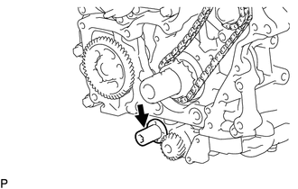
Install a new gasket and oil pump relief valve plug to the timing chain cover sub-assembly.
- Torque:
- 46 N*m { 469 kgf*cm, 34 ft.*lbf }
-
-
INSTALL TIMING CHAIN COVER PLATE
-
INSTALL TIMING CHAIN COVER SUB-ASSEMBLY
-
INSTALL FRONT CRANKSHAFT OIL SEAL
-
INSTALL REAR ENGINE OIL SEAL RETAINER
-
Clean and degrease the contact surfaces of the rear engine oil seal retainer and cylinder block sub-assembly.
-
Text in Illustration *a Seal Packing Apply seal packing to the rear engine oil seal retainer in the areas indicated in the illustration.
Seal packing Toyota Genuine Seal Packing Black, Three Bond 1207B or equivalent Standard seal diameter 3.0 to 4.0 mm (0.118 to 0.157 in.) Note
-
Remove any engine oil from the contact surface.
-
Install the rear engine oil seal retainer within 3 minutes and tighten the bolts within 10 minutes after applying seal packing.
-
Do not add engine oil within 2 hours of installation.
-
Do not start the engine for at least 2 hours after the installation.
-
-
Install the rear engine oil seal retainer to the cylinder block sub-assembly, and then install the 5 bolts.
- Torque:
- 10 N*m { 102 kgf*cm, 7 ft.*lbf }
-
-
INSTALL REAR ENGINE OIL SEAL
-
INSTALL OIL STRAINER SUB-ASSEMBLY
-
Install a new gasket and oil strainer sub-assembly to the cylinder block sub-assembly with the 5 bolts in several steps in the sequence shown in the illustration.
- Torque:
- 12 N*m { 122 kgf*cm, 9 ft.*lbf }
Tech Tips
Make sure that the claw of the gasket faces the oil strainer sub-assembly.
-
-
INSTALL OIL PAN SUB-ASSEMBLY
-
INSTALL NO. 2 OIL PAN SUB-ASSEMBLY
-
INSTALL ENGINE OIL LEVEL SENSOR
-
INSTALL CRANKSHAFT POSITION SENSOR
-
INSTALL CRANKSHAFT POSITION SENSOR HARNESS BRACKET
-
Install the crankshaft position sensor harness bracket to the cylinder block sub-assembly with the bolt.
- Torque:
- 10 N*m { 102 kgf*cm, 7 ft.*lbf }
-
Connect the crankshaft position sensor connector.
-
-
INSTALL NO. 1 CYLINDER BLOCK INSULATOR
-
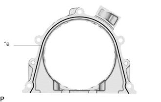
Install the No. 1 cylinder block insulator to the cylinder block sub-assembly.
-
-
INSTALL NO. 5 CYLINDER BLOCK INSULATOR
-
Install the No. 5 cylinder block insulator to the cylinder block sub-assembly.
-
-
INSTALL CYLINDER HEAD COVER SUB-ASSEMBLY
-
INSTALL OIL FILLER CAP GASKET
-
Install the oil filler cap gasket to the oil filler cap sub-assembly.
-
-
INSTALL OIL FILLER CAP SUB-ASSEMBLY
-
Install the oil filler cap sub-assembly to the cylinder head cover sub-assembly.
-
-
INSTALL NOZZLE HOLDER GASKET
-
TEMPORARILY INSTALL INJECTOR ASSEMBLY
-
INSTALL OIL FILTER BRACKET
-
Install 2 new O-rings to the cylinder block sub-assembly.
-
Install the oil filter bracket to the cylinder block sub-assembly with the 2 nuts and bolt.
- Torque:
- 21 N*m { 214 kgf*cm, 15 ft.*lbf }
-
-
INSTALL OIL FILTER UNION
-
Using a 27 mm deep socket wrench, install the oil filter union to the oil filter bracket.
- Torque:
- 29 N*m { 300 kgf*cm, 22 ft.*lbf }
-
-
INSTALL OIL FILTER SUB-ASSEMBLY
-
INSTALL OIL COOLER ASSEMBLY
-
INSTALL FRONT NO. 1 ENGINE MOUNTING BRACKET RH
-
Install the front No. 1 engine mounting bracket RH to the cylinder block sub-assembly with the 4 bolts.
- Torque:
- 68 N*m { 693 kgf*cm, 50 ft.*lbf }
-
-
INSTALL GENERATOR BRACKET SUB-ASSEMBLY
-
Install the generator bracket sub-assembly to the cylinder head sub-assembly and timing chain case assembly with the 4 bolts.
- Torque:
- 21 N*m { 214 kgf*cm, 15 ft.*lbf }
-
-
INSTALL NO. 3 CYLINDER BLOCK INSULATOR
-
Install the No. 3 cylinder block insulator to the cylinder block sub-assembly.
-
-
INSTALL FRONT NO. 1 ENGINE MOUNTING BRACKET LH
-
Install the front No. 1 engine mounting bracket LH to the cylinder block sub-assembly with the 4 bolts.
- Torque:
- 68 N*m { 693 kgf*cm, 50 ft.*lbf }
-
-
INSTALL NO. 2 CYLINDER BLOCK INSULATOR
-
Install the No. 2 cylinder block insulator to the front No. 1 engine mounting bracket LH.
-
-
INSTALL NO. 1 ENGINE HANGER
-
Install the No. 1 engine hanger to the cylinder head sub-assembly with the 2 bolts.
- Torque:
- 26 N*m { 265 kgf*cm, 19 ft.*lbf }
-