ENGINE ASSEMBLY INSTALLATION

PROCEDURE
-
INSTALL FRONT ENGINE MOUNTING INSULATOR (for LH Side)
-
Install the front engine mounting insulator to the front engine mounting bracket with the nut.
- Torque:
- 64 N*m { 653 kgf*cm, 47 ft.*lbf }
-
Connect the vacuum hose to the front engine mounting insulator.
-
-
INSTALL ENGINE WIRE
-
Install the engine wire to the engine assembly.
-
-
INSTALL ENGINE HANGER
-
REMOVE ENGINE ASSEMBLY TO ENGINE STAND
Note
-
Pay attention to the angle of the sling device as the engine assembly or engine hangers may be damaged or deformed if the angle is incorrect.
-
With the exception of installing the engine assembly to an engine stand or removing the engine assembly from an engine stand, do not perform any work on the engine assembly while it is suspended, as doing so is dangerous.
-
Attach the engine sling device and hang the engine assembly with the chain block.
-
Remove the engine assembly from the engine stand.
-
-
INSTALL ENGINE ASSEMBLY
-
Slowly lower the engine assembly into the engine compartment.
-
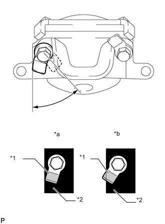
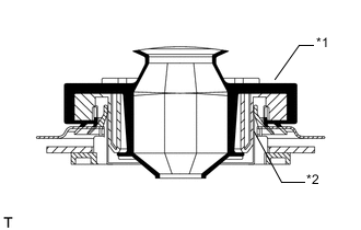
Text in Illustration *1 Claw (Stopper) *2 Bracket *a Correct *b Incorrect Install the engine assembly to the body with the 4 bolt and 4 nuts.
- Torque:
- 40 N*m { 408 kgf*cm, 30 ft.*lbf }
Tech Tips
For RHD vehicles only:
When tightening the nut closer to the rear of the vehicle for the engine mounting bracket on the right side, make sure that the claw (stopper) of the bolt does not protrude past the rear edge of the bracket.
-
Remove the 3 bolts, No. 1 engine hanger upper and No. 2 engine hanger.
-
-
INSTALL REAR END PLATE
-
Install the rear end plate to the cylinder block sub-assembly with the bolt.
- Torque:
- 10 N*m { 102 kgf*cm, 7 ft.*lbf }
-
-
INSTALL FLYWHEEL SUB-ASSEMBLY
-
Clean the bolts and their holes.
-
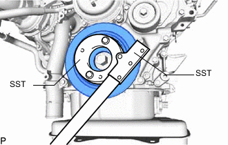
Using SST, hold the crankshaft pulley.
- SST
- 09213-58014
- 09330-00021
-
for Manual Transmission:
Install the flywheel sub-assembly to the crankshaft with the 8 bolts.
- Torque:
- 178 N*m { 1815 kgf*cm, 131 ft.*lbf }
Note
Do not start the engine for at least 1 hour after installation.
-
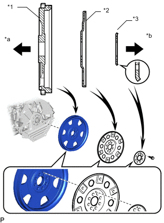
Text in Illustration *1 Flywheel Sub-assembly *2 Pump Impeller Drive Plate *3 Rear Drive Plate Spacer *a Engine Side *b Transmission Side for Automatic Transmission:
Install the flywheel sub-assembly, the pump impeller drive plate and the rear drive plate spacer to the crankshaft with the 8 bolts.
Note
-
Align either hole in the pump impeller drive plate and either hole in the rear drive plate spacer with the knock pin of the flywheel sub-assembly, and then install the flywheel sub-assembly, the pump impeller drive plate and the rear drive plate spacer to the crankshaft.
-
Do not start the engine for at least 1 hour after installation.
Tech Tips
As the rear drive plate spacer and pump impeller drive plate are not reversible, be sure to install them in the direction shown in the illustration.
-
-
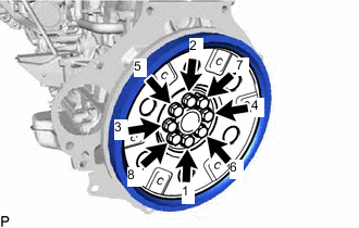
for Automatic Transmission:
Install and uniformly tighten and tighten the 8 bolts in several steps in the sequence shown in the illustration.
- Torque:
- 178 N*m { 1815 kgf*cm, 131 ft.*lbf }
-
w/o Viscous Heater:
Install the crankshaft pulley cover to the crankshaft pulley with the 4 bolts.
- Torque:
- 21 N*m { 214 kgf*cm, 15 ft.*lbf }
-
w/ Viscous Heater:
Install the crankshaft pulley cover and viscous heater crankshaft pulley to the crankshaft pulley with the 4 bolts.
- Torque:
- 25 N*m { 250 kgf*cm, 18 ft.*lbf }
-
-
INSTALL CLUTCH DISC ASSEMBLY (for Manual Transmission)
-
INSTALL CLUTCH COVER ASSEMBLY (for Manual Transmission)
-
INSPECT AND ADJUST CLUTCH COVER ASSEMBLY
-
INSTALL AUTOMATIC TRANSMISSION ASSEMBLY (for Automatic Transmission)
-
INSTALL DRIVE PLATE AND TORQUE CONVERTER CLUTCH SETTING BOLT (for Automatic Transmission)
-
INSTALL MANUAL TRANSMISSION UNIT ASSEMBLY (for Manual Transmission)
-
INSTALL PROPELLER SHAFT ASSEMBLY
-
INSTALL FRONT PROPELLER SHAFT ASSEMBLY
-
INSTALL FRONT EXHAUST PIPE ASSEMBLY
-
INSTALL VISCOUS HEATER WITH MAGNET CLUTCH ASSEMBLY (w/ Viscous Heater)
-
Install the viscous heater with magnet clutch assembly to the No. 1 viscous heater bracket with the 2 bolts.
- Torque:
- 39 N*m { 398 kgf*cm, 29 ft.*lbf }
-
Connect the connector to the viscous heater with magnet clutch assembly.
-
-
INSTALL WATER HOSE SUB-ASSEMBLY B (w/ Viscous Heater)
-
Install the water hose sub-assembly B to the No. 2 water pipe and water outlet sub-assembly, slide the 4 clamps secure the hoses.
-
Connect the water hose sub-assembly B to the water inlet with the bolt.
- Torque:
- 10 N*m { 102 kgf*cm, 7 ft.*lbf }
-
-
CONNECT COOLER COMPRESSOR ASSEMBLY
-
Temporarily install the cooler compressor assembly and stud bolt to the compressor mounting bracket.
-
Using an E8 "TORX" socket wrench, tighten the stud bolt.
- Torque:
- 10 N*m { 102 kgf*cm, 7 ft.*lbf }
-
Install the 3 bolts and nut.
- Torque:
- 25 N*m { 250 kgf*cm, 18 ft.*lbf }
-
Connect the connector to the cooler compressor assembly.
-
-
INSTALL GENERATOR ASSEMBLY
-
CONNECT VANE PUMP ASSEMBLY
-
Connect the vane pump assembly to the generator bracket with the 2 bolts.
- Torque:
- 21 N*m { 214 kgf*cm, 15 ft.*lbf }
-
Connect the 2 connectors to the vane pump assembly.
-
-
INSTALL WATER HOSE SUB-ASSEMBLY
-
INSTALL BATTERY TRAY
-
INSTALL BATTERY
-
INSTALL BATTERY HOLD DOWN CLAMP
-
Install the battery hold down clamp with the 2 nuts.
- Torque:
- 6.0 N*m { 61 kgf*cm, 53 in.*lbf }
-
-
CONNECT ENGINE WIRE
-
Connect the engine room main wire to the battery with the nut.
- Torque:
- 7.5 N*m { 76 kgf*cm, 66 in.*lbf }
-
Attach the clamp.
-
Connect the No. 2 engine wire to the body with the bolt.
- Torque:
- 8.5 N*m { 87 kgf*cm, 75 in.*lbf }
-
Attach the 2 claws and install the nut.
- Torque:
- 11 N*m { 112 kgf*cm, 8 ft.*lbf }
-
Attach the 3 claws to install the No. 1 relay block cover upper.
-
-
CONNECT NO. 2 FUEL HOSE
-
Connect the No. 2 fuel hose to the No. 3 nozzle leakage pipe, slide the clamp to secure the hose.
-
Install the 2 clamps to the No. 2 fuel hose.
-
-
CONNECT NO. 1 FUEL HOSE
-
Connect the No. 1 fuel hose to the No. 2 fuel pipe, slide the clamp to secure the hose.
-
Install the clamp to the No. 1 fuel hose.
-
-
CONNECT VANE PUMP OIL RESERVOIR SUB-ASSEMBLY
-
CONNECT UREA TANK FILLER PIPE ASSEMBLY (w/ Urea SCR System)
-
INSTALL AIR TUBE ASSEMBLY
-
INSTALL NO. 2 INTERCOOLER AIR HOSE
-
INSTALL AIR CLEANER CASE
-
INSTALL AIR CLEANER FILTER ELEMENT SUB-ASSEMBLY
-
INSTALL AIR CLEANER CAP WITH AIR CLEANER HOSE
-
INSTALL NO. 1 ENGINE COVER SUB-ASSEMBLY
-
CONNECT ENGINE WIRE
-
Text in Illustration *1 Grommet *2 Wire Harness Support Attach the grommet to the wire harness support.
-
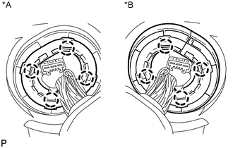
Text in Illustration *A for LHD *B for RHD Pass the wire harness into the vehicle and install the wire harness support.
-
Attach the clamp and connect the engine wire to the bracket.
-
Install the ECM Click here.
-
-
INSTALL RADIATOR ASSEMBLY
-
INSTALL COWL TOP VENTILATOR LOUVER SUB-ASSEMBLY
-
INSTALL HOOD SUB-ASSEMBLY
-
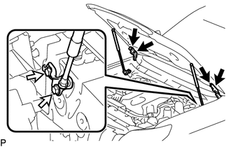
Install the hood sub-assembly with the 8 bolts.
- Torque:
- Bolt A
- 13 N*m { 133 kgf*cm, 10 ft.*lbf }
- Bolt B
- 18 N*m { 178 kgf*cm, 13 ft.*lbf }
Text in Illustration 
Bolt A 
Bolt B -
Connect the washer nozzle hose.
-
-
ADJUST HOOD SUB-ASSEMBLY
-
CONNECT CABLE TO NEGATIVE BATTERY TERMINAL
Note
When disconnecting the cable, some systems need to be initialized after the cable is reconnected Click here.
-
ADD ENGINE OIL
-
ADD AUTOMATIC TRANSMISSION FLUID (for Automatic Transmission)
-
ADD MANUAL TRANSMISSION OIL (for Manual Transmission)
-
BLEED AIR FROM FUEL SYSTEM
-
ADD ENGINE COOLANT
-
INSPECT FOR COOLANT LEAK
-
INSPECT ENGINE OIL LEVEL
-
INSPECT ENGINE IDLE SPEED AND MAXIMUM SPEED
-
INSTALL REAR ENGINE UNDER COVER ASSEMBLY
-
Install the rear engine under cover with the 4 bolts.
- Torque:
- 29 N*m { 296 kgf*cm, 21 ft.*lbf }
-
-
INSTALL TRANSMISSION UNDER COVER
-
Install the transmission under cover with the 2 bolts.
- Torque:
- 29 N*m { 296 kgf*cm, 21 ft.*lbf }
-
-
INSTALL NO. 1 ENGINE UNDER COVER SUB-ASSEMBLY
-
Install the No. 1 engine under cover with the 4 bolts.
- Torque:
- 29 N*m { 296 kgf*cm, 21 ft.*lbf }
-
-
INSTALL FRONT BUMPER LOWER COVER
-
Install the front bumper lower cover with the clip and 5 bolts.
- Torque:
- 8.0 N*m { 82 kgf*cm, 71 ft.*lbf }
-