ENGINE UNIT INSTALLATION

CAUTION / NOTICE / HINT
Note
-
When replacing the injectors (including shuffling the injectors between the cylinders), common rail or cylinder head, it is necessary to replace the injection pipes with new ones.
-
When replacing the fuel supply pump, common rail, cylinder block, cylinder head, cylinder head gasket or timing gear case, it is necessary to replace the fuel inlet pipe with a new one.
PROCEDURE
-
INSTALL FRONT NO. 1 ENGINE MOUNTING BRACKET RH
-
Install the 2 engine mounting brackets with the 8 bolts.
- Torque:
- 68 N*m { 694 kgf*cm, 50 ft.*lbf }
-
-
INSTALL NO. 2 CYLINDER BLOCK INSULATOR
-
Install the No. 2 cylinder block insulator.
-
-
INSTALL NO. 1 VACUUM PIPE
-
Install the No. 1 vacuum pipe with the bolt.
- Torque:
- 8.0 N*m { 82 kgf*cm, 70 in.*lbf }
-
-
INSTALL NO. 1 OIL PAN COVER SUB-ASSEMBLY
-
Install the No. 1 oil pan cover with the 4 bolts.
- Torque:
- 9.0 N*m { 92 kgf*cm, 80 in.*lbf }
-
-
INSTALL NO. 1 VACUUM TRANSMITTING PIPE SUB-ASSEMBLY
-
Install the No. 1 vacuum transmitting pipe with the bolt and nut.
- Torque:
- for bolt
- 13 N*m { 133 kgf*cm, 10 ft.*lbf }
- for nut
- 8.0 N*m { 82 kgf*cm, 71 in.*lbf }
-
-
INSTALL OIL COOLER COVER SUB-ASSEMBLY
-
Install the oil cooler cover with the 13 bolts.
- Torque:
- 13 N*m { 133 kgf*cm, 10 ft.*lbf }
-
-
INSTALL NO. 2 VACUUM TRANSMITTING PIPE SUB-ASSEMBLY
-
Install the No. 2 vacuum transmitting pipe with the 2 nuts.
- Torque:
- 13 N*m { 133 kgf*cm, 10 ft.*lbf }
-
Connect the vacuum hose.
-
-
INSTALL NO. 3 VACUUM TRANSMITTING PIPE SUB-ASSEMBLY
-
Install the No. 3 vacuum transmitting pipe with the bolt.
- Torque:
- 18 N*m { 184 kgf*cm, 13 ft.*lbf }
-
Connect the vacuum hose.
-
-
INSTALL OIL FILTER SUB-ASSEMBLY
-
INSTALL NO. 1 INJECTION PUMP PROTECTOR
-
Install the No. 1 injection pump protector with the 2 bolts.
- Torque:
- 29 N*m { 296 kgf*cm, 21 ft.*lbf }
-
-
INSTALL SUPPLY PUMP ASSEMBLY
-
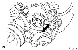
Check that the injection gear in the timing gear case moves back and forth smoothly.
-
Install the pump drive shaft pulley and No. 2 camshaft timing pulley flange with the 4 bolts.
- Torque:
- 31 N*m { 316 kgf*cm, 23 ft.*lbf }
-
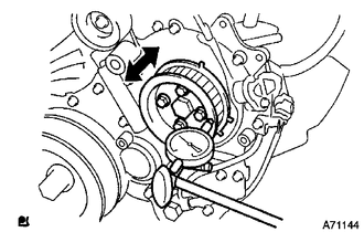
Move the pump drive shaft pulley back and forth to check the thrust clearance of the injection pump drive shaft.
Standard thrust clearance 0.15 to 0.55 mm (0.00590 to 0.0217 in.) If the clearance is not within the specified range, disassemble and reassemble the supply pump and pump drive shaft pulley. Then repeat the step above.
-
-
INSTALL COMMON RAIL ASSEMBLY
-
Install the common rail with the 2 bolts.
- Torque:
- 38 N*m { 387 kgf*cm, 28 ft.*lbf }
-
-
INSTALL FUEL INLET PIPE SUB-ASSEMBLY
-
Temporarily install the fuel inlet pipe with the union nuts.
Note
-
When replacing the fuel supply pump, it is necessary to replace the fuel inlet pipe with a new one.
-
Keep the fuel inlet pipe free of foreign matter.
-
-
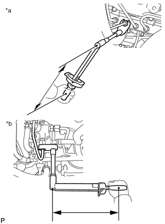
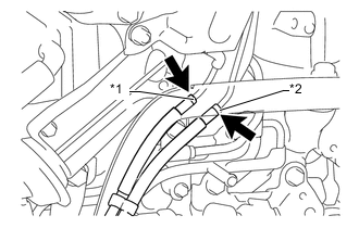
Text in Illustration *a for Common Rail Side *b for Fuel Supply Pump Side Using a 17 mm union nut wrench, tighten the fuel inlet pipe union nut on the common rail side.
- Torque:
- 35 N*m { 357 kgf*cm, 26 ft.*lbf }
Note
Use the formula to calculate special torque values for situations where a union nut wrench is combined with a torque wrench Click here.
-
Using a 17 mm union nut wrench, tighten the fuel inlet pipe union nut on the fuel supply pump side.
- Torque:
- 35 N*m { 357 kgf*cm, 26 ft.*lbf }
Note
Use the formula to calculate special torque values for situations where a union nut wrench is combined with a torque wrench Click here.
-
-
INSTALL NO. 2 INTAKE MANIFOLD INSULATOR
-
Install the No. 2 intake manifold insulator.
-
-
INSTALL INTAKE MANIFOLD
-
INSTALL INTAKE MANIFOLD INSULATOR
-
INSTALL NO. 2 NOZZLE LEAKAGE PIPE ASSEMBLY
-
INSTALL NO. 4 INJECTION PIPE SUB-ASSEMBLY
-
INSTALL VACUUM CONTROL VALVE SET
-
INSTALL INTAKE PIPE STAY
-
INSTALL MANIFOLD STAY WITH VACUUMSWITCHING VALVE
-
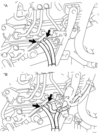
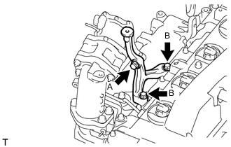
Text in Illustration *A w/o EGR System *B w/ EGR System *1 Blue Mark *2 White Mark Install the manifold stay with vacuum switching valve with the 2 bolts and connect the No. 3 vacuum transmitting hose assembly and No. 4 vacuum transmitting hose assembly.
- Torque:
- 19 N*m { 194 kgf*cm, 14 ft.*lbf }
Note
Make sure the vacuum hose color matches the connection area color.
-
w/ EGR Cooler:
Connect the No. 3 vacuum transmitting hose.
-
Text in Illustration *1 Yellow Mark *2 Pink Mark w/ EGR System:
Connect the No. 2 vacuum transmitting hose and No. 3 vacuum transmitting hose assembly.
Note
-
Make sure the vacuum hose color matches the connection area color.
-
Push on the hose until it reaches the bent part of the pipe.
-
-
Connect the No. 1 vacuum transmitting hose.
-
-
INSTALL GLOW PLUG ASSEMBLY
-
Using a 12 mm socket wrench, install the 4 glow plugs.
- Torque:
- 13 N*m { 133 kgf*cm, 10 ft.*lbf }
-
-
INSTALL NO. 1 INTAKE MANIFOLD INSULATOR
-
Install the No. 1 intake manifold insulator.
-
-
INSTALL NO. 1 GLOW PLUG CONNECTOR
-
Install the glow plug connector with the 4 nuts. Uniformly tighten the nuts.
- Torque:
- 2.2 N*m { 22 kgf*cm, 19 in.*lbf }
-
Install the 4 screw grommets.
-
-
INSTALL WATER OUTLET
-
Install a new gasket and the water outlet with the 2 bolts.
- Torque:
- 19 N*m { 194 kgf*cm, 14 ft.*lbf }
-
-
INSTALL NO. 2 EGR HOLE COVER PLATE (w/o EGR System)
-
Install a new gasket and the No. 2 EGR hole cover plate with the 2 nuts.
- Torque:
- 13 N*m { 133 kgf*cm, 10 ft.*lbf }
-
-
INSTALL NO. 2 INTAKE AIR CONNECTOR (w/o EGR System)
-
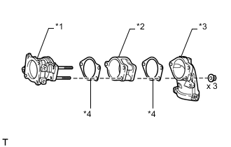
Text in Illustration *1 No. 2 Intake Air Connector *2 No. 1 Intake Air Connector *3 Intake Air Connector *4 Gasket Install the No. 2 intake air connector, No. 1 intake air connector, intake air connector and 2 new gaskets with the 3 nuts as shown in the illustration.
- Torque:
- 20 N*m { 204 kgf*cm, 15 ft.*lbf }
-
-
INSTALL INTAKE AIR CONNECTOR (w/o EGR System)
-
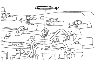
Set a new gasket on the intake manifold.
Note
Make sure the claws of the gasket face the intake manifold as shown in the illustration.
-
Install the intake air connector with the 3 bolts.
- Torque:
- 20 N*m { 204 kgf*cm, 15 ft.*lbf }
Note
Tighten the bolts in the order shown in the illustration.
-
-
INSTALL AIR CONNECTOR STAY (w/o EGR System)
-
Temporarily install the air connector stay with the 3 bolts.
-
Tighten the bolt labeled A.
- Torque:
- 20 N*m { 204 kgf*cm, 15 ft.*lbf }
-
Tighten the 2 bolts labeled B.
- Torque:
- 20 N*m { 204 kgf*cm, 15 ft.*lbf }
-
-
INSTALL INJECTION PIPE (w/o EGR System)
-
INSTALL THROTTLE BODY BRACKET (w/o EGR System)
-
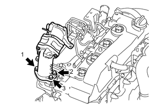
Install the throttle body bracket with the 2 bolts.
- Torque:
- 20 N*m { 204 kgf*cm, 15 ft.*lbf }
-
Install the gas filter with gas filter bracket with the bolt.
- Torque:
- 20 N*m { 204 kgf*cm, 15 ft.*lbf }
-
Connect the vacuum hose.
-
-
INSTALL NO. 2 EGR VALVE ASSEMBLY (w/ EGR Cooler)
-
INSTALL EGR COOLER WITH PIPE (w/ EGR System with EGR Cooler)
-
TEMPORARILY INSTALL ELECTRIC EGR CONTROL VALVE ASSEMBLY (w/ EGR System with EGR Cooler)
-
TIGHTEN ELECTRIC EGR CONTROL VALVE ASSEMBLY (w/ EGR System with EGR Cooler)
-
INSTALL NO. 1 EGR PIPE SUB-ASSEMBLY (w/ EGR System without EGR Cooler)
-
TEMPORARILY INSTALL ELECTRIC EGR CONTROL VALVE ASSEMBLY (w/ EGR System without EGR Cooler)
-
TIGHTEN ELECTRIC EGR CONTROL VALVE ASSEMBLY (w/ EGR System without EGR Cooler)
-
INSTALL AIR CONNECTOR STAY (w/ EGR System)
-
INSTALL ELECTRIC VACUUM REGULATING VALVE ASSEMBLY (w/ EGR System)
-
INSTALL EGR VALVE BRACKET (w/ EGR System)
-
INSTALL INJECTION PIPE (w/ EGR System)
-
CONNECT NO. 4 WATER BY-PASS HOSE (w/ EGR System with EGR Cooler)
-
CONNECT NO. 3 WATER BY-PASS HOSE (w/ EGR System with EGR Cooler)
-
INSTALL CRANKSHAFT PULLEY
-
INSTALL NO. 1 TIMING BELT IDLER SUB-ASSEMBLY
-
INSTALL TIMING BELT
-
INSTALL NO. 1 TIMING BELT COVER
-
INSTALL CRANKSHAFT POSITION SENSOR
-
Attach the clamp and install the crankshaft position sensor with the bolt.
- Torque:
- 8.5 N*m { 87 kgf*cm, 75 in.*lbf }
-
-
INSTALL CAMSHAFT POSITION SENSOR
-
Install the camshaft position sensor with the bolt.
- Torque:
- 8.5 N*m { 87 kgf*cm, 75 in.*lbf }
-
-
INSTALL ENGINE COOLANT TEMPERATURE SENSOR
-
INSTALL VANE PUMP ASSEMBLY
-
Install a new O-ring and the vane pump with the 2 nuts.
- Torque:
- 41 N*m { 418 kgf*cm, 30 ft.*lbf }
-
-
INSTALL VACUUM PUMP ASSEMBLY
-
Install 2 new O-rings to the vacuum pump.
-
Install the vacuum pump with the 2 nuts.
- Torque:
- 21 N*m { 210 kgf*cm, 15 ft.*lbf }
-
-
INSTALL TIMING GEAR COVER INSULATOR
-
Install the timing gear cover insulator with the bolt.
- Torque:
- 8.0 N*m { 82 kgf*cm, 71 in.*lbf }
-
-
INSTALL ENGINE OIL LEVEL SENSOR
-
Install a new gasket and the engine oil level sensor with the 4 bolts.
- Torque:
- 8.0 N*m { 82 kgf*cm, 71 ft.*lbf }
-
-
INSTALL NO. 2 WATER BY-PASS PIPE SUB-ASSEMBLY
-
Install the No. 2 water by-pass pipe with the 2 bolts and 2 nuts.
- Torque:
- 8.0 N*m { 82 kgf*cm, 71 ft.*lbf }
-
Connect the 2 hoses.
-
-
INSTALL THERMOSTAT
-
Install a new gasket to the thermostat.
Note
When installing the gasket to the thermostat, be careful not to deform the gasket. Make sure that the gasket is properly installed to the thermostat, as shown in the illustration.
-
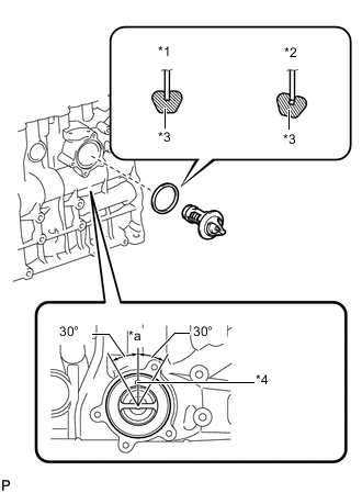
Text in Illustration *1 CORRECT *2 INCORRECT *3 Gasket *4 Jiggle Valve *a Upward Install the thermostat to the cylinder block with the jiggle valve facing straight upward.
Tech Tips
The jiggle valve may be set within 30° of either side of the prescribed position.
-
-
INSTALL WATER INLET
-
Install the water inlet with the 3 bolts.
- Torque:
- 13 N*m { 133 kgf*cm, 10 ft.*lbf }
-
-
INSTALL COMPRESSOR ELBOW STAY
-
Install the compressor elbow stay with the 2 bolts.
- Torque:
- 19 N*m { 194 kgf*cm, 14 ft.*lbf }
-
-
INSTALL NO. 2 CYLINDER HEAD COVER SUB-ASSEMBLY
-
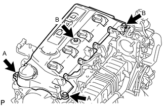
Install the No. 2 cylinder head cover with the 4 bolts.
- Torque:
- for bolt A
- 18 N*m { 184 kgf*cm, 13 ft.*lbf }
- for bolt B
- 8.0 N*m { 82 kgf*cm, 71 in.*lbf }
-
-
INSTALL EXHAUST MANIFOLD WITH TURBOCHARGER
-
INSTALL TURBINE OUTLET ELBOW
-
CONNECT NO. 1 TURBO WATER HOSE
-
INSTALL NO. 1 EXHAUST MANIFOLD HEATINSULATOR
-
INSTALL NO. 1 TURBO INSULATOR
-
INSTALL COMPRESSOR INLET ELBOW
-
INSTALL ENGINE OIL LEVEL DIPSTICK GUIDE
-
INSTALL VENTILATION PIPE
-
INSTALL NO. 1 COMPRESSOR MOUNTING BRACKET
-
Install the No. 1 compressor mounting bracket with the 5 bolts.
- Torque:
- 21 N*m { 214 kgf*cm, 15 ft.*lbf }
-
-
INSTALL GENERATOR BRACKET
-
Install the generator bracket with the bolts.
- Torque:
- 21 N*m { 214 kgf*cm, 15 ft.*lbf }
-
-
INSTALL GENERATOR ASSEMBLY
-
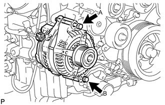
Install the generator with the 2 bolts.
- Torque:
- for bolt A
- 62 N*m { 632 kgf*cm, 46 ft.*lbf }
- for bolt B
- 21 N*m { 214 kgf*cm, 15 ft.*lbf }
-