ENGINE UNIT REASSEMBLY

PROCEDURE
-
INSTALL REAR CRANKSHAFT OIL SEAL
-
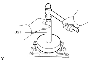
Using SST and a hammer, tap in a new oil seal until its surface is flush with the rear oil seal retainer edge.
- SST
- 09518-36030
- 09950-70010 ( 09951-07100 )
-
Apply MP grease to the lip of the oil seal.
-
-
INSTALL SUPPLY PUMP OIL SEAL
-
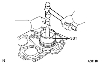
Using SST and a hammer, tap in a new oil seal until its surface is flush with the timing gear cover edge.
- SST
- 09223-15020
- 09502-12010
- 09950-70010 ( 09951-07100 )
-
Apply MP grease to the lip of the oil seal.
-
-
INSTALL FRONT CRANKSHAFT OIL SEAL
-
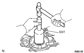
Using SST and a hammer, tap in a new oil seal until its surface is flush with the timing gear cover edge.
- SST
- 09214-76011
-
Apply MP grease to the lip of the oil seal.
-
-
INSTALL REAR ENGINE OIL SEAL RETAINER
-
Remove any old seal packing (FIPG material) from the oil pan and cylinder block.
-
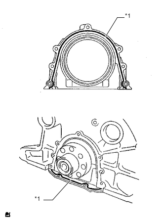
Text in Illustration *1 Seal Packing Apply seal packing to the places shown in the illustration.
Seal packing Toyota Genuine Seal Packing Black, Three Bond 1207B or equivalent Standard seal diameter 4 mm (0.157 in.) Note
After applying seal packing, install the rear engine oil seal retainer within 3 minutes and tighten the bolts within 15 minutes.
-
Install the retainer with the 5 bolts. Alternately tighten the 5 bolts in several passes.
- Torque:
- 13 N*m { 133 kgf*cm, 10 ft.*lbf }
-
-
INSTALL NO. 2 BALANCESHAFT DRIVEN GEAR
-
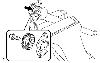
Mount the balanceshaft between aluminum plates in a vise.
Note
Be careful not to damage the balanceshaft.
-
Align the balanceshaft knock pin with the knock pin hole. Then install the balanceshaft thrust washer and balanceshaft driven gear.
-
Install the bolt.
- Torque:
- 36 N*m { 367 kgf*cm, 27 ft.*lbf }
-
-
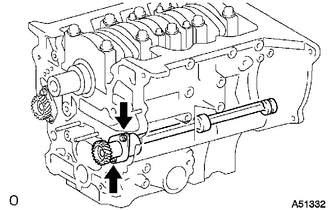
INSTALL NO. 2 BALANCESHAFT SUB-ASSEMBLY
-
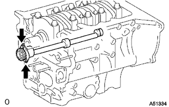
Install the balanceshaft with the 2 bolts.
- Torque:
- 13 N*m { 133 kgf*cm, 10 ft.*lbf }
-
-
INSTALL NO. 1 BALANCESHAFT DRIVEN GEAR
-
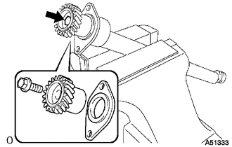
Mount the balanceshaft between aluminum plates in a vise.
Note
Be careful not to damage the balanceshaft.
-
Align the balanceshaft knock pin with the knock pin hole. Then install the balanceshaft thrust washer and balanceshaft driven gear.
-
Install the bolt.
- Torque:
- 36 N*m { 367 kgf*cm, 27 ft.*lbf }
-
-
INSTALL NO. 1 BALANCESHAFT SUB-ASSEMBLY
-
Install the balanceshaft with the 2 bolts.
- Torque:
- 13 N*m { 133 kgf*cm, 10 ft.*lbf }
-
-
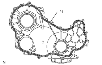
INSTALL TIMING GEAR CASE ASSEMBLY
-
Remove any old seal packing (FIPG material).
-
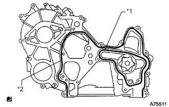
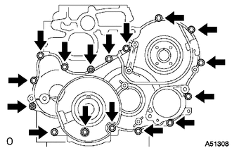
Text in Illustration *1 New Gasket *2 Seal Packing Apply seal packing to the timing gear case as shown in the illustration.
Seal packing Toyota Genuine Seal Packing Black, Three Bond 1207B or equivalent Standard seal diameter 5 mm (0.197 in.) Note
After applying seal packing, install the timing gear case assembly within 3 minutes and tighten the bolts within 15 minutes.
-
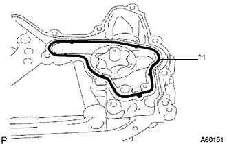
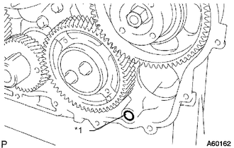
Text in Illustration *1 New Gasket Install a new gasket to the groove of the timing gear case.
-
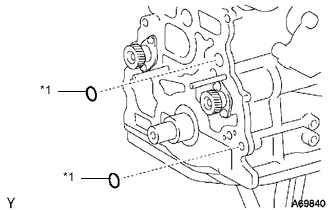
Text in Illustration *1 New O-Ring Install 2 new O-rings to the cylinder block.
-
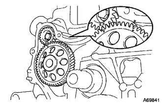
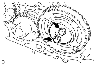
Align the "2" marks of the balanceshaft driven gear No. 1 and oil pump drive gear.
-
Align the mark on the oil pump drive gear with the mark on the timing gear case.
-
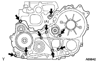
Install the timing gear case with the union bolt and 8 bolts.
- Torque:
- for union bolt (A)
- 16 N*m { 163 kgf*cm, 12 ft.*lbf }
- for bolt
- 13 N*m { 133 kgf*cm, 10 ft.*lbf }
-
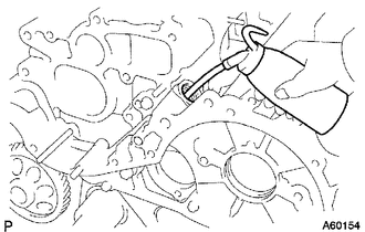
Remove the screw plug and gasket.
-
Pour approximately 50 cc (3.05 cu. in.) of engine oil into the oil pump.
-
Install a new gasket and the screw plug.
- Torque:
- 44 N*m { 449 kgf*cm, 32 ft.*lbf }
-
-
INSTALL OIL PAN SUB-ASSEMBLY
-
Remove any old seal packing (FIPG material) and be careful not to drop any oil on the contact surfaces of the cylinder block, rear oil seal retainer and oil pan.
-
Install a new gasket to the cylinder block.
-
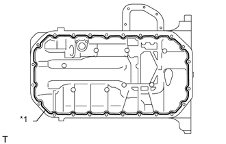
Text in Illustration *1 Seal Packing Apply seal packing in a continuous line as shown in the illustration.
Seal packing Toyota Genuine Seal Packing Black, Three Bond 1207B or equivalent Standard seal diameter 4 mm (0.157 in.) Note
-
Remove any oil from the contact surface.
-
Install the oil pan within 3 minutes after applying seal packing.
-
Do not start the engine for at least 2 hours after installation.
-
-
Install the oil pan with the 22 bolts and 2 nuts.
- Torque:
- 15 N*m { 148 kgf*cm, 11 ft.*lbf }
-
-
INSTALL OIL STRAINER SUB-ASSEMBLY
-
Install a new gasket and the oil strainer with the 2 nuts.
- Torque:
- 8.0 N*m { 82 kgf*cm, 71 in.*lbf }
-
-
INSTALL NO. 2 OIL PAN SUB-ASSEMBLY
-
Remove any old seal packing (FIPG material).
-
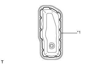
Text in Illustration *1 Seal Packing Apply seal packing to the No. 2 oil pan as shown in the illustration.
Seal packing Toyota Genuine Seal Packing Black, Three Bond 1207B or equivalent Standard seal diameter 4 mm (0.157 in.) Note
-
Remove any oil from the contact surface.
-
Install the No. 2 oil pan within 3 minutes after applying seal packing.
-
Do not start the engine for at least 2 hours after installation.
-
-
Install the No. 2 oil pan with the 13 bolts and 2 nuts.
- Torque:
- 9.0 N*m { 92 kgf*cm, 80 in.*lbf }
-
-
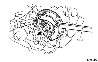
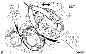
INSTALL CRANKSHAFT TIMING GEAR
-
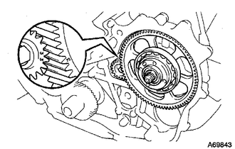
Position the crankshaft timing gear with timing mark 1 facing forward.
-
Align the key groove of the crankshaft timing gear with the set key on the crankshaft.
-
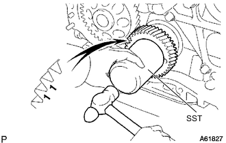
Using SST and a hammer, tap on the timing gear to install it.
- SST
- 09223-00010
-
-
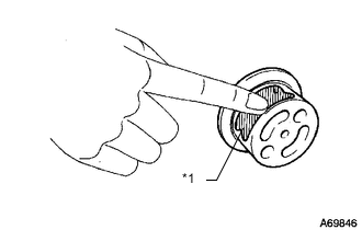
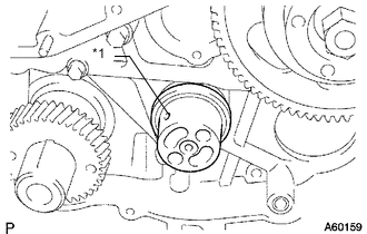
INSTALL INJECTION GEAR
-
Install a new O-ring and the supply pump with the 2 nuts.
- Torque:
- 21 N*m { 214 kgf*cm, 15 ft.*lbf }
-
Temporarily install the injection gear with the nut.
Tech Tips
Fit the key (protrusion) of the supply pump into the key slot of the injection gear.
-
Align the "3" marks of the balanceshaft driven gear No. 2 and injection gear.
-
Text in Illustration *1 New O-Ring Install a new O-ring to the injection gear.
-
Install the injection gear set nut.
-
Using SST, tighten the nut.
- SST
- 09960-10010 ( 09962-01000, 09963-01000 )
- Torque:
- 64 N*m { 653 kgf*cm, 47 ft.*lbf }
-
-
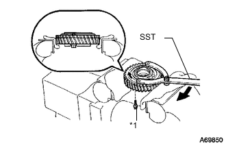
INSTALL NO. 2 IDLE SUB GEAR
-
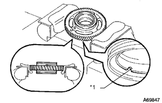
Text in Illustration *1 Cutout Mark Mount the No. 1 idle gear in a vise.
Tech Tips
Make sure the cutout mark of the idle gear faces down.
Note
Be careful not to damage the gear.
-
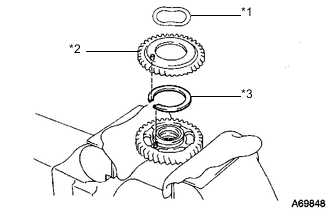
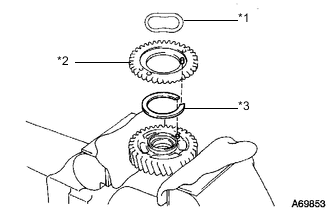
Text in Illustration *1 Wave Washer *2 No. 2 Idle Sub Gear *3 Idle Gear Spring Install the idle gear spring.
-
Install the No. 2 idle sub gear.
-
Install the wave washer.
Tech Tips
Fit the pins on the gears between the spring ends.
-
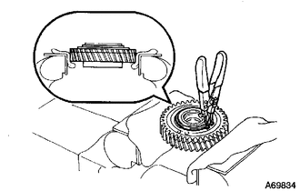
Using snap ring pliers, install the shaft snap ring.
-
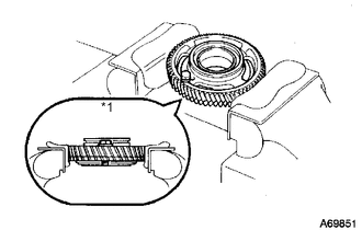
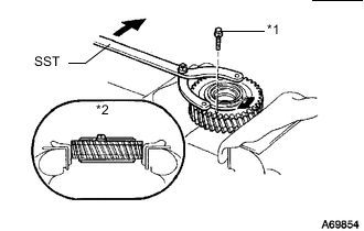
Text in Illustration *1 Service Bolt Using SST, align the holes of the No. 1 idle gear and No. 2 idle sub gear by turning the No. 2 idle sub gear clockwise and install a service bolt.
- SST
- 09960-10010 ( 09962-01000, 09963-00700 )
-
Remove the No. 1 idle gear from the vise and turn it upside down.
-
-
INSTALL NO. 1 IDLE SUB GEAR
-
Text in Illustration *1 Upward Mount the No. 1 idle gear and No. 2 idle sub gear in a vise.
Note
Be careful not to damage the gears.
-
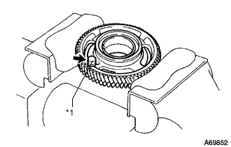
Text in Illustration *1 Service Bolt Remove the service bolt.
-
Text in Illustration *1 Wave Washer *2 No. 1 Idle Sub Gear *3 Idle Gear Spring Install the idle gear spring.
-
Install the No. 1 idle sub gear.
-
Install the wave washer.
Tech Tips
Fit the pins on the gears between the spring ends.
-
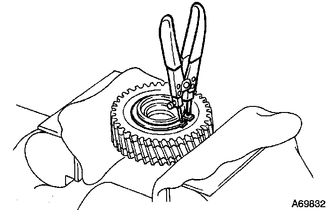
Using a snap ring pliers, install the shaft snap ring.
-
Text in Illustration *1 Service Bolt *2 Upward Using SST, align the holes of the No. 1 idler gear and No. 1 idle sub gear by turning the No. 1 idle sub gear clockwise, and install the service bolt.
- SST
- 09960-10010 ( 09962-01000, 09963-00600 )
-
-
INSTALL NO. 1 IDLE GEAR SHAFT
-
Text in Illustration *1 Engine Oil Apply a coat of engine oil to the No. 1 idle gear shaft.
-
Text in Illustration *1 Oil Hole Install the gear shaft as shown in the illustration.
-
-
INSTALL NO. 1 IDLE GEAR
-
Text in Illustration *1 Turn Align the "5" timing marks of the idle gear and crankshaft timing gear.
-
Using SST, turn the injection gear and align the "4" timing marks of the idle gear and injection gear, and then mesh the gears.
- SST
- 09960-10010 ( 09962-01000, 09963-00700 )
-
Text in Illustration *1 Service Bolt Position the thrust plate with the protrusion facing forward.
-
Align the bolt holes and install the thrust plate with the 2 bolts.
- Torque:
- 50 N*m { 510 kgf*cm, 37 ft.*lbf }
-
Remove the service bolt.
-
-
INSTALL NO. 1 CRANKSHAFT POSITION SENSOR PLATE
-
Align the key groove of the sensor plate with the set key.
-
Install the sensor plate with the cupped side facing outward.
-
-
INSTALL TIMING GEAR COVER
-
Remove any old seal packing (FIPG material).
-
Text in Illustration *1 Seal Packing Apply seal packing to the timing gear cover as shown in the illustration.
Seal packing Toyota Genuine Seal Packing Black, Three Bond 1207B or equivalent Standard seal diameter 4 mm (0.157 in.) Note
After applying seal packing, install the timing gear cover within 3 minutes and tighten the bolts within 15 minutes.
-
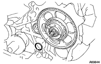
Text in Illustration *1 New O-Ring Install a new O-ring to the timing gear case.
-
Install the timing gear cover with the 14 bolts and 2 nuts.
- Torque:
- 13 N*m { 133 kgf*cm, 10 ft.*lbf }
-
-
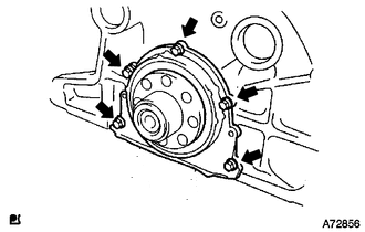
INSTALL WATER PUMP ASSEMBLY
-
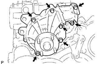
Install a new gasket and the water pump with the 5 bolts and 2 nuts.
- Torque:
- 13 N*m { 133 kgf*cm, 10 ft.*lbf }
-
-
INSTALL CYLINDER HEAD GASKET
-
INSTALL CYLINDER HEAD SUB-ASSEMBLY
-
INSTALL VALVE LIFTER
-
Install the valve lifter.
-
Check that the valve lifter rotates smoothly by hand.
-
-
INSTALL CAMSHAFT
-
INSPECT AND ADJUST VALVE CLEARANCE
-
INSTALL CYLINDER BLOCK INSULATOR
-
INSTALL NO. 2 TIMING BELT COVER
-
INSTALL CAMSHAFT TIMING PULLEY
-
INSTALL INJECTOR ASSEMBLY
-
INSPECT FOR FUEL LEAK
-
INSTALL CYLINDER HEAD COVER SUB-ASSEMBLY
-
INSTALL NOZZLE HOLDER SEAL
-
INSTALL OIL FILLER CAP SUB-ASSEMBLY