ENGINE UNIT REMOVAL

PROCEDURE
-
REMOVE GENERATOR ASSEMBLY
-
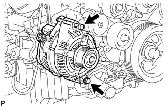
Remove the 2 bolts and generator.
-
-
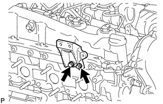
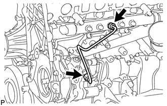
REMOVE GENERATOR BRACKET
-
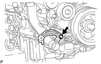
Remove the bolt and generator bracket.
-
-
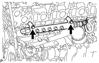
REMOVE NO. 1 COMPRESSOR MOUNTING BRACKET
-
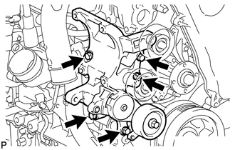
Remove the 5 bolts and No. 1 compressor mounting bracket.
-
-
REMOVE VENTILATION PIPE
-
REMOVE ENGINE OIL LEVEL DIPSTICK GUIDE
-
REMOVE COMPRESSOR INLET ELBOW
-
REMOVE NO. 1 TURBO INSULATOR
-
REMOVE NO. 1 EXHAUST MANIFOLD HEATINSULATOR
-
DISCONNECT NO. 1 TURBO WATER HOSE
-
REMOVE TURBINE OUTLET ELBOW
-
REMOVE TURBOCHARGER STAY
-
REMOVE TURBO OIL INLET PIPE SUB-ASSEMBLY
-
REMOVE EXHAUST MANIFOLD WITH TURBOCHARGER
-
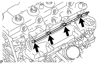
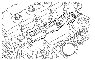
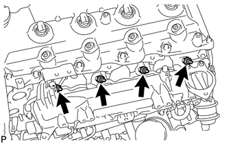
REMOVE NO. 2 CYLINDER HEAD COVER SUB-ASSEMBLY
-
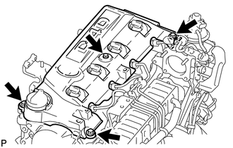
Remove the 4 bolts and No. 2 cylinder head cover.
-
-
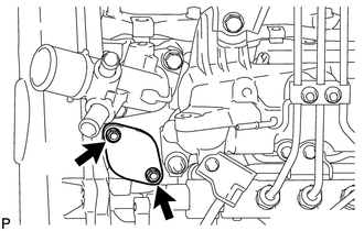
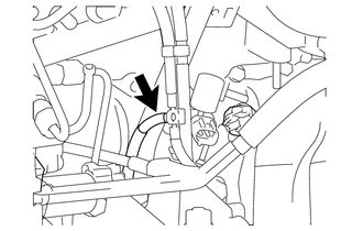
REMOVE COMPRESSOR ELBOW STAY
-
Remove the 2 bolts and compressor elbow stay.
-
-
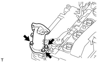
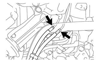
REMOVE WATER INLET
-
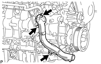
Remove the 3 bolts and water inlet.
-
-
REMOVE THERMOSTAT
-
Remove the thermostat.
-
Remove the gasket from the thermostat.
-
-
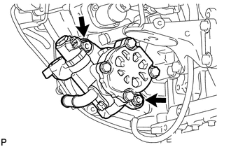
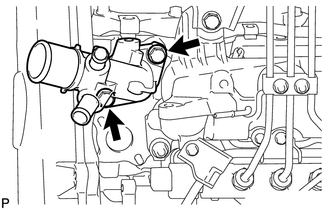
REMOVE NO. 2 WATER BY-PASS PIPE SUB-ASSEMBLY
-
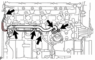
Disconnect the 2 hoses.
-
Remove the 2 bolts, 2 nuts and No. 2 water by-pass pipe.
-
-
REMOVE ENGINE OIL LEVEL SENSOR
-
Remove the 4 bolts and engine oil level sensor.
-
Cut away part of the gasket and remove the gasket from the engine oil level sensor.
Tech Tips
Remove only the outer part of the gasket.
-
-
REMOVE TIMING GEAR COVER INSULATOR
-
Remove the bolt and gear cover insulator.
-
-
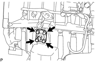
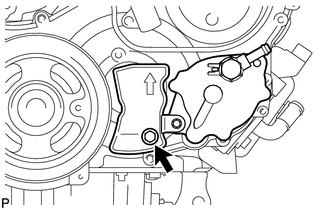
REMOVE VACUUM PUMP ASSEMBLY
-
Remove the 2 nuts, vacuum pump and 2 O-rings.
-
-
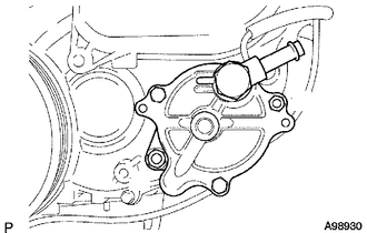
REMOVE VANE PUMP ASSEMBLY
-
Remove the 2 nuts, vane pump and O-ring.
-
-
REMOVE ENGINE COOLANT TEMPERATURE SENSOR
-
REMOVE CAMSHAFT POSITION SENSOR
-
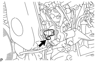
Remove the bolt and camshaft position sensor.
-
-
REMOVE CRANKSHAFT POSITION SENSOR
-
Detach the clamp and remove the bolt and crankshaft position sensor.
-
-
REMOVE NO. 1 TIMING BELT COVER
-
REMOVE TIMING BELT
-
REMOVE NO. 1 TIMING BELT IDLER SUB-ASSEMBLY
-
REMOVE CRANKSHAFT PULLEY
-
DISCONNECT NO. 3 WATER BY-PASS HOSE (w/ EGR System with EGR Cooler)
-
DISCONNECT NO. 4 WATER BY-PASS HOSE (w/ EGR System with EGR Cooler)
-
REMOVE INJECTION PIPE (w/ EGR System)
-
REMOVE AIR CONNECTOR STAY (w/ EGR System)
-
REMOVE EGR VALVE BRACKET (w/ EGR System)
-
REMOVE ELECTRIC VACUUM REGULATING VALVE ASSEMBLY (w/ EGR System)
-
REMOVE NO. 2 INTAKE AIR CONNECTOR (w/ EGR System)
-
REMOVE INTAKE AIR CONNECTOR (w/ EGR System)
-
REMOVE ELECTRIC EGR CONTROL VALVE ASSEMBLY WITHNO. 2 EGR VALVE AND EGR COOLER (w/ EGR System with EGR Cooler)
-
REMOVE ELECTRIC EGR CONTROL VALVEASSEMBLY WITH NO. 1 EGR PIPE SUB-ASSEMBLY (w/ EGR System without EGR Cooler)
-
REMOVE ELECTRIC EGR CONTROL VALVE ASSEMBLY (w/ EGR System)
-
REMOVE EGR VALVE ADAPTER (w/ EGR System with EGR Cooler)
-
REMOVE NO. 2 EGR VALVE ASSEMBLY (w/ EGR System with EGR Cooler)
-
REMOVE THROTTLE BODY BRACKET (w/o EGR System)
-
Disconnect the vacuum hose.
-
Remove the bolt and gas filter with gas filter bracket.
-
Remove the 2 bolts and throttle body bracket.
-
-
REMOVE INJECTION PIPE (w/o EGR System)
-
REMOVE AIR CONNECTOR STAY (w/o EGR System)
-
Remove the 3 bolts and air connector stay.
-
-
REMOVE NO. 2 INTAKE AIR CONNECTOR (w/o EGR System)
-
Remove the 3 nuts.
-
Remove the No. 2 intake air connector, No. 1 intake air connector and 2 gaskets.
-
-
REMOVE INTAKE AIR CONNECTOR (w/o EGR System)
-
Remove the 3 bolts, intake air connector and gasket.
-
-
REMOVE NO. 2 EGR HOLE COVER PLATE (w/o EGR System)
-
Remove the 2 nut, gasket and No. 2 EGR hole cover plate.
-
-
REMOVE WATER OUTLET
-
Remove the 2 bolts, gasket and water outlet.
-
-
REMOVE NO. 1 GLOW PLUG CONNECTOR
-
Remove the 4 screw grommets, 4 nuts and No. 1 glow plug connector.
-
-
REMOVE NO. 1 INTAKE MANIFOLD INSULATOR
-
Remove the No. 1 intake manifold insulator.
-
-
REMOVE GLOW PLUG ASSEMBLY
-
Using a 12 mm deep socket wrench, remove the 4 glow plugs.
-
-
REMOVE MANIFOLD STAY WITH VACUUMSWITCHING VALVE
-
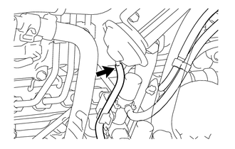
Disconnect the No. 1 vacuum transmitting hose.
-
w/ EGR System:
Disconnect the No. 2 vacuum transmitting hose and No. 3 vacuum transmitting hose assembly.
-
w/ EGR Cooler:
Disconnect the No. 3 vacuum transmitting hose.
-
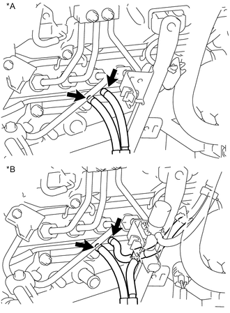
Text in Illustration *A w/o EGR System *B w/ EGR System Disconnect the No. 3 vacuum transmitting hose assembly and No. 4 vacuum transmitting hose assembly.
-
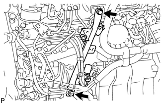
Remove the 2 bolts and manifold stay with vacuum switching valve.
-
-
REMOVE INTAKE PIPE STAY
-
REMOVE VACUUM CONTROL VALVE SET
-
REMOVE NO. 4 INJECTION PIPE SUB-ASSEMBLY
-
REMOVE NO. 2 NOZZLE LEAKAGE PIPE ASSEMBLY
-
REMOVE INTAKE MANIFOLD INSULATOR
-
REMOVE INTAKE MANIFOLD
-
REMOVE NO. 2 INTAKE MANIFOLD INSULATOR
-
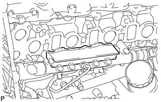
Remove the No. 2 intake manifold insulator.
-
-
REMOVE FUEL INLET PIPE SUB-ASSEMBLY
-
Loosen the union nuts and remove the fuel inlet pipe.
-
-
REMOVE COMMON RAIL ASSEMBLY
-
Remove the 2 bolts and common rail.
Note
Do not remove the pressure discharge valve or fuel pressure sensor.
-
-
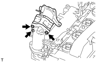
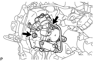
REMOVE SUPPLY PUMP ASSEMBLY
-
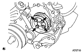
Remove the 4 bolts indicated by the arrows in the illustration.
-
Remove the No. 2 camshaft timing pulley flange and pump drive shaft pulley.
-
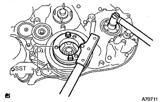
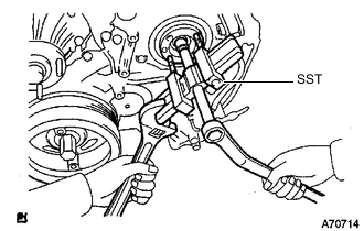
Remove the set nut and O-ring while holding the crankshaft pulley using SST.
- SST
- 09213-58014
- 09330-00021
-
Loosen the 2 nuts.
-
Using SST, disconnect the supply pump from the injection gear.
- SST
- 09950-50013 ( 09951-05010, 09952-05010, 09953-05020, 09954-05021 )
Note
Apply lubricant to the threads and tip of SST (center bolt) before using it.
-
Remove the 2 nuts and supply pump.
Note
-
Do not hold or carry the fuel supply pump by holding the pipe.
-
The fuel supply pump must be kept horizontal.
-
-
Remove the O-ring.
-
-
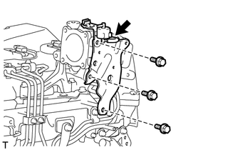
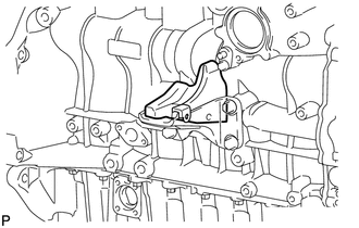
REMOVE NO. 1 INJECTION PUMP PROTECTOR
-
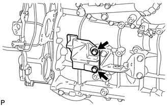
Remove the 2 bolts and No. 1 injection pump protector.
-
-
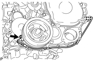
REMOVE OIL FILTER SUB-ASSEMBLY
-
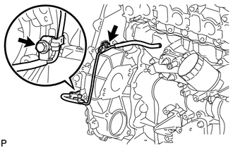
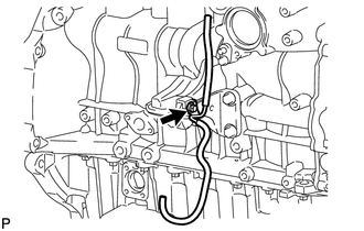
REMOVE NO. 3 VACUUM TRANSMITTING PIPE SUB-ASSEMBLY
-
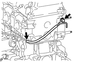
Disconnect the vacuum hose.
-
Remove the bolt and No. 3 vacuum transmitting pipe.
-
-
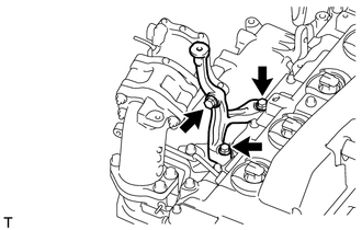
REMOVE NO. 2 VACUUM TRANSMITTING PIPE SUB-ASSEMBLY
-
Disconnect the vacuum hose.
-
Remove the 2 nuts and No. 2 vacuum transmitting pipe.
-
-
REMOVE OIL COOLER COVER SUB-ASSEMBLY
-
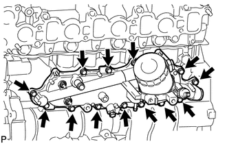
Remove the 13 bolts and oil cooler cover.
-
-
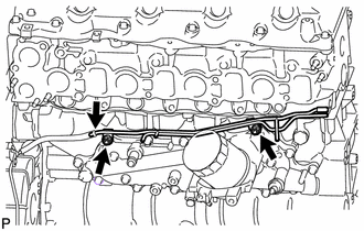
REMOVE NO. 1 VACUUM TRANSMITTING PIPE SUB-ASSEMBLY
-
Remove the bolt, nut and No. 1 vacuum transmitting pipe.
-
-
REMOVE NO. 1 OIL PAN COVER SUB-ASSEMBLY
-
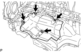
Remove the 4 bolts and No. 1 oil pan cover.
-
-
REMOVE NO. 1 VACUUM PIPE
-
Remove the bolt and No. 1 vacuum pipe.
-
-
REMOVE NO. 2 CYLINDER BLOCK INSULATOR
-
Remove the No. 2 cylinder block insulator.
-
-
REMOVE FRONT NO. 1 ENGINE MOUNTING BRACKET RH
-
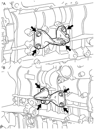
Text in Illustration *A for LH Side *B for RH Side Remove the 8 bolts and 2 engine mounting brackets.
-