ENGINE ASSEMBLY INSTALLATION

PROCEDURE
-
INSTALL FRONT ENGINE MOUNTING INSULATOR
-
Install the 2 front engine mounting insulator with the 2 nuts.
- Torque:
- 76 N*m { 775 kgf*cm, 56 ft.*lbf }
-
-
INSTALL ENGINE WIRE
-
Install the engine wire to the engine.
-
-
REMOVE ENGINE FROM ENGINE STAND
-
Text in Illustration *1 No. 1 Engine Hanger *2 No. 2 Engine Hanger Install 2 engine hangers with 2 bolts as shown in the illustration.
Tech Tips
Part No.
No. 1 engine hanger 12284-30020 No. 2 engine hanger 12282-67030 Bolt 91552-81014 and 91642-81030 - Torque:
- for No. 1 engine hanger
- 25 N*m { 255 kgf*cm, 18 ft.*lbf }
- for No. 2 engine hanger
- 60 N*m { 612 kgf*cm, 44 ft.*lbf }
Note
Install the engine hangers with new bolts.
-
Attach an engine sling device and hang the engine with a chain block.
-
Remove the engine from the engine stand.
-
-
INSTALL REAR END PLATE
-
Install the rear end plate with the bolts.
- Torque:
- 8.0 N*m { 82 kgf*cm, 71 in.*lbf }
-
-
INSTALL PUMP IMPELLER DRIVE PLATE (for Automatic Transmission)
-
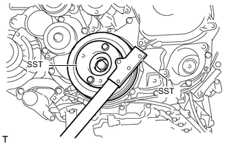
Using SST, hold the crankshaft pulley.
- SST
- 09213-58014
- 09330-00021
-
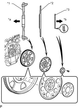
Text in Illustration *1 Flywheel and Ring Gear *2 Pump Impeller Drive Plate *3 Rear Drive Plate Spacer *a Engine Side *b Transmission Side Install the flywheel and ring gear, the pump impeller drive plate and the rear drive plate spacer to the crankshaft.
Note
Align either hole in the pump impeller drive plate and either hole in the rear drive plate spacer with the knock pin of the flywheel and ring gear, and then install the flywheel and ring gear, the pump impeller drive plate and the rear drive plate spacer to the crankshaft.
Tech Tips
As the rear drive plate spacer and pump impeller drive plate are not reversible, be sure to install them in the direction shown in the illustration.
-
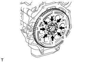
Uniformly install and tighten the 8 bolts in several steps in the sequence shown in the illustration.
Note
Do not start the engine for at least an hour after installing the flywheel and ring gear.
- Torque:
- 178 N*m { 1815 kgf*cm, 131 ft.*lbf }
-
-
INSTALL FLYWHEEL SUB-ASSEMBLY (for Manual Transmission)
-
Clean the bolts and their holes.
-
Apply adhesive to 2 or 3 threads at the end of each bolt.
Adhesive Toyota Genuine Adhesive 1324, Three Bond 1324 or equivalent -
Using SST, hold the crankshaft pulley.
- SST
- 09213-58014
- 09330-00021
-
Install the flywheel to the crankshaft.
-
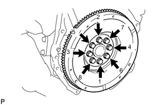
Uniformly install and tighten the 8 bolts in the sequence shown in the illustration.
- Torque:
- 178 N*m { 1815 kgf*cm, 131 ft.*lbf }
Note
Do not start the engine for at least 1 hour after installation.
-
-
INSTALL CLUTCH DISC ASSEMBLY (for Manual Transmission)
-
INSTALL CLUTCH COVER ASSEMBLY (for Manual Transmission)
-
INSPECT AND ADJUST CLUTCH COVER ASSEMBLY
-
INSTALL ENGINE ASSEMBLY
-
Slowly lower the engine into the engine compartment.
-
Install the engine with the 4 bolts and 4 nuts.
- Torque:
- 40 N*m { 408 kgf*cm, 30 ft.*lbf }
Tech Tips
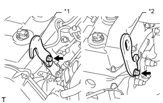
For RHD vehicles only:
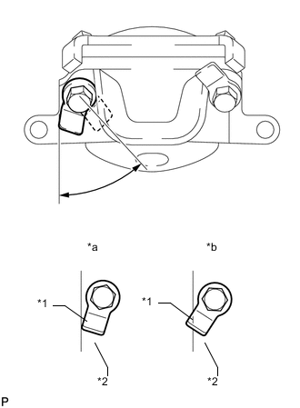
When tightening the nut closer to the rear of the vehicle for the engine mounting bracket on the right side, make sure that the claw (stopper) of the bolt does not protrude past the rear edge of the bracket.
Text in Illustration *1 Claw (Stopper) *2 Bracket *a Correct *b Incorrect -
Remove the 2 bolts and 2 engine hangers.
-
-
INSTALL REAR NO. 1 ENGINE MOUNTING INSULATOR
Tech Tips
Perform this procedure only when replacement of the rear No. 1 engine mounting insulator is necessary.
-
Install the 4 bolts and rear No. 1 engine mounting insulator.
- Torque:
- 65 N*m { 663 kgf*cm, 48 ft.*lbf }
-
-
INSTALL AUTOMATIC TRANSMISSION ASSEMBLY (for Automatic Transmission)
-
Install the automatic transmission Click here.
-
-
INSTALL DRIVE PLATE AND TORQUE CONVERTER CLUTCH SETTING BOLT (for Automatic Transmission)
-
INSTALL MANUAL TRANSMISSION ASSEMBLY (for Manual Transmission)
-
Install the manual transmission Click here.
-
-
INSTALL OIL PAN INSULATOR
-
Install the oil pan insulator with the 2 bolts.
- Torque:
- 18 N*m { 178 kgf*cm, 13 ft.*lbf }
-
-
INSTALL PROPELLER SHAFT ASSEMBLY
-
INSTALL FRONT PROPELLER SHAFT ASSEMBLY
-
INSTALL FRONT EXHAUST PIPE ASSEMBLY
-
INSTALL STARTER ASSEMBLY (for 2.2 kW Type)
-
INSTALL STARTER ASSEMBLY (for 2.7 kW Type)
-
INSTALL STARTER ASSEMBLY (for 3.0 kW Type)
-
CONNECT ENGINE WIRE
-
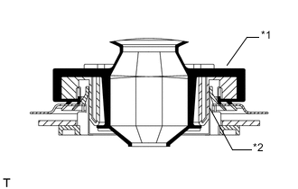
Text in Illustration *1 Grommet *2 Wire Harness Support Attach the grommet to the wire harness support.
-
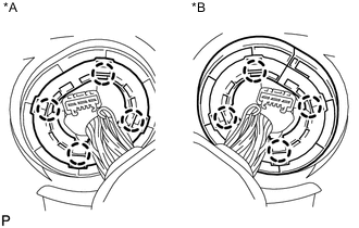
Text in Illustration *A for LHD *B for RHD Pass the wire harness into the vehicle and install the wire harness support.
-
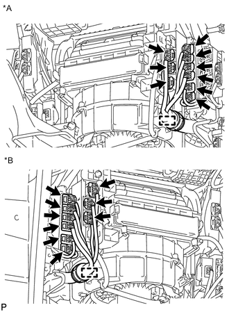
Text in Illustration *A for LHD *B for RHD Connect the 9 connectors and attach the clamp.
-
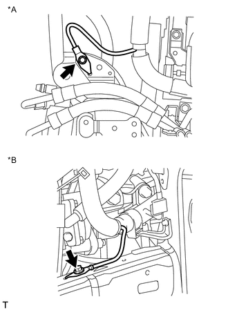
Text in Illustration *A w/ KDSS *B w/o KDSS Install the bolt.
- Torque:
- 19 N*m { 194 kgf*cm, 14 ft.*lbf }
-
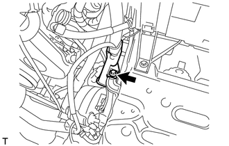
Connect the wire harness protector with the bolt.
- Torque:
- 8.0 N*m { 82 kgf*cm, 71 in.*lbf }
-
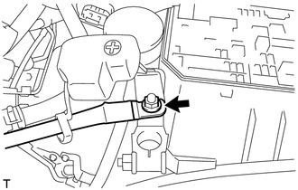
Connect the engine wire with the nut.
- Torque:
- 7.5 N*m { 76 kgf*cm, 66 in.*lbf }
-
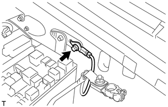
Install the bolt.
- Torque:
- 8.5 N*m { 87 kgf*cm, 75 in.*lbf }
-
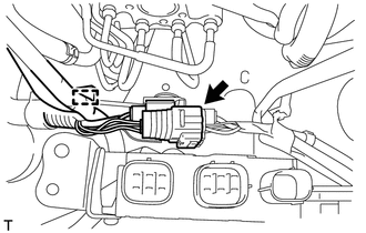
Attach the clamp and connect the connector.
-
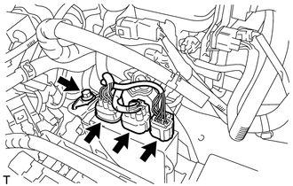
Connect the 3 injection driver connectors and install the bolt.
- Torque:
- 8.0 N*m { 82 kgf*cm, 71 in.*lbf }
-
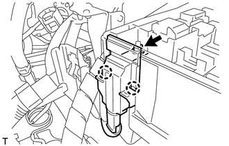
Attach the 2 claws and install the nut.
- Torque:
- 11 N*m { 112 kgf*cm, 8 ft.*lbf }
-
Install the No. 1 relay block cover.
-
-
INSTALL GLOVE COMPARTMENT DOOR SUB-ASSEMBLY
-
Install the glove compartment door Click here
-
-
CONNECT FUEL HOSE
-
Connect the No. 1 fuel hose and No. 2 fuel hose.
-
-
CONNECT OUTLET HEATER WATER HOSE
-
Connect the outlet heater water hose.
-
-
CONNECT INLET HEATER WATER HOSE
-
Connect the inlet heater water hose.
-
-
CONNECT PRESSURE FEED TUBE ASSEMBLY
-
Connect the pressure feed tube and a new gasket with the union bolt.
- Torque:
- 50 N*m { 510 kgf*cm, 37 ft.*lbf }
-
Connect the power steering oil pressure switch connector.
-
-
CONNECT VANE PUMP OIL RESERVOIR SUB-ASSEMBLY
-
Temporarily install the vane pump oil reservoir with the 3 bolts.
-
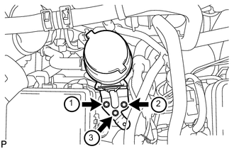
Tighten the 3 bolts of the vane pump oil reservoir in the order shown in the illustration.
- Torque:
- 8.0 N*m { 82 kgf*cm, 71 in.*lbf }
-
-
INSTALL FUEL FILTER ASSEMBLY
-
Install the fuel filter Click here.
-
-
INSTALL DIESEL THROTTLE BODY ASSEMBLY
-
Install the diesel throttle body Click here.
-
-
CONNECT COOLER COMPRESSOR ASSEMBLY (w/ Air Conditioning System)
-
Connect the cooler compressor with the 4 bolts.
- Torque:
- 25 N*m { 250 kgf*cm, 18 ft.*lbf }
-
Connect the compressor connector.
-
-
INSTALL NO. 1 VISCOUS HEATER BRACKET SUB-ASSEMBLY (for Cold Area Specification Vehicles)
-
Install the No. 1 viscous heater bracket with the 4 bolts.
- Torque:
- 45 N*m { 459 kgf*cm, 33 ft.*lbf }
-
-
INSTALL VISCOUS HEATER WITH MAGNET CLUTCH ASSEMBLY (for Cold Area Specification Vehicles)
-
Install the viscous heater with magnet clutch with the 2 bolts.
- Torque:
- 45 N*m { 459 kgf*cm, 33 ft.*lbf }
-
Connect the water by-pass hose and water hose.
-
Connect the viscous heater connector.
-
-
INSTALL COMPRESSOR OUTLET ELBOW
-
INSTALL AIR CLEANER CASE SUB-ASSEMBLY
-
INSTALL AIR CLEANER FILTER ELEMENT SUB-ASSEMBLY
-
INSTALL AIR CLEANER CAP SUB-ASSEMBLY
-
INSTALL NO. 1 AIR CLEANER HOSE
-
INSTALL BATTERY TRAY
-
INSTALL BATTERY
-
INSTALL BATTERY HOLD DOWN CLAMP
-
Install the battery hold down clamp with the 2 nuts.
- Torque:
- 6.0 N*m { 61 kgf*cm, 53 in.*lbf }
-
-
INSTALL RADIATOR ASSEMBLY
-
Install the radiator Click here.
-
-
ADD POWER STEERING FLUID
-
ADD MANUAL TRANSMISSION OIL (for Manual Transmission)
-
INSPECT MANUAL TRANSMISSION OIL (for Manual Transmission)
-
ADD ENGINE OIL
-
CONNECT CABLE TO NEGATIVE BATTERY TERMINAL
Note
When disconnecting the cable, some systems need to be initialized after the cable is reconnected Click here.
-
BLEED AIR FROM FUEL SYSTEM
-
ADD ENGINE COOLANT
-
INSPECT FOR COOLANT LEAK
-
INSTALL COWL TOP VENTILATOR LOUVER SUB-ASSEMBLY
-
Install the cowl top ventilator louver Click here.
-
-
INSTALL HOOD SUB-ASSEMBLY
-
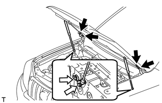
Install the hood with the 8 bolts.
- Torque:
- for bolt A
- 13 N*m { 133 kgf*cm, 10 ft.*lbf }
- for bolt B
- 18 N*m { 184 kgf*cm, 13 ft.*lbf }
Text in Illustration 
Bolt A 
Bolt B -
Connect the washer nozzle hose.
-
-
ADD AUTOMATIC TRANSMISSION FLUID (for Automatic Transmission)
-
Add automatic transmission fluid Click here.
-
-
INSPECT FOR POWER STEERING FLUID LEAK
-
INSPECT FOR OIL LEAK
-
INSPECT FOR FUEL LEAK
-
INSPECT FOR EXHAUST GAS LEAK
-
INSPECT ENGINE IDLE SPEED AND MAXIMUMSPEED
-
INSPECT ENGINE OIL LEVEL
-
INSTALL REAR ENGINE UNDER COVER ASSEMBLY
-
Install the rear engine under cover with the 4 bolts.
- Torque:
- 29 N*m { 296 kgf*cm, 21 ft.*lbf }
-
-
INSTALL TRANSMISSION UNDER COVER
-
Install the transmission under cover with the 2 bolts.
- Torque:
- 29 N*m { 296 kgf*cm, 21 ft.*lbf }
-
-
INSTALL NO. 1 ENGINE UNDER COVER SUB-ASSEMBLY
-
Install the No. 1 engine under cover with the 4 bolts.
- Torque:
- 29 N*m { 296 kgf*cm, 21 ft.*lbf }
-
-
INSTALL FRONT BUMPER LOWER COVER
-
Install the lower front bumper cover with the clip and 5 bolts.
- Torque:
- 8.0 N*m { 82 kgf*cm, 71 in.*lbf }
-