CYLINDER HEAD GASKET INSTALLATION
CAUTION / NOTICE / HINT
Note
-
When replacing the injectors (including shuffling the injectors between the cylinders), common rail or cylinder head, it is necessary to replace the injection pipes with new ones.
-
When replacing the fuel supply pump, common rail, cylinder block, cylinder head, cylinder head gasket or timing gear case, it is necessary to replace the fuel inlet pipe with a new one.
PROCEDURE
-
INSTALL CYLINDER HEAD GASKET
-
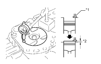
Text in Illustration *1 Measuring Tip *2 Protrusion Find where the piston head protrudes most by slowly turning the crankshaft clockwise and counterclockwise.
-
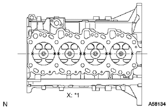
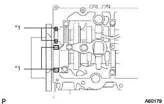
Text in Illustration *1 Measuring Point Measure the piston protrusion of each cylinder at 2 points as shown in the illustration.
-
For the piston protrusion value of each cylinder, use the average of the 2 measurements of each cylinder.
Piston protrusion 0.005 to 0.255 mm (0.000197 to 0.0100 in.) Tech Tips
After installing the piston and connecting rod assembly, if the protrusion is not as specified, remove the piston and connecting rod assembly and reinstall them.
-
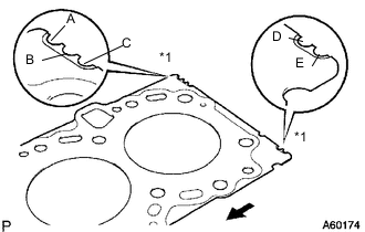
Text in Illustration *1 Cutout Mark 
Front Select a new cylinder head gasket.
Tech Tips
New cylinder head gaskets are available in 5 sizes, and are marked A, B, C, D or E.
New Cylinder Head Gasket Thickness Mark Specified Condition A 0.80 to 0.90 mm (0.0315 to 0.0354 in.) B 0.85 to 0.95 mm (0.0335 to 0.0374 in.) C 0.90 to 1.00 mm (0.0354 to 0.0394 in.) D 0.95 to 1.05 mm (0.0374 to 0.0413 in.) E 1.00 to 1.10 mm (0.0394 to 0.0433 in.)
-
Select the largest piston protrusion value from the measurements made. Then select a new gasket to the table below.
Gasket Size Item Specified Condition Piston protrusion 0.005 to 0.054 mm (0.000197 to 0.00213 in.) 0.055 to 0.104 mm (0.00217 to 0.00409 in.) 0.105 to 0.154 mm (0.00413 to 0.00606 in.) 0.155 to 0.204 mm (0.00610 to 0.00803 in.) 0.205 to 0.255 mm (0.00807 to 0.0100 in.) Use gasket A B C D E
-
-
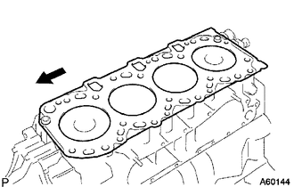
Place the cylinder head gasket on the cylinder block.
Text in Illustration Front Note
Make sure the gasket is installed facing the proper direction.
-
-
INSTALL CYLINDER HEAD SUB-ASSEMBLY
Tech Tips
-
The cylinder head bolts are tightened in 3 progressive steps.
-
If any bolt is broken or deformed, replace it Click here.
-
Place the cylinder head on the cylinder head gasket.
-
Apply a light coat of engine oil on the threads and under the heads of the cylinder head bolts.
-
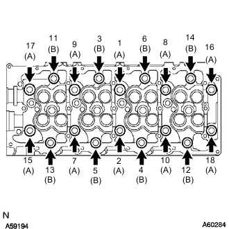
Install the 18 washers with the 18 cylinder head bolts, and uniformly tighten the bolts, in several passes in the sequence shown in the illustration.
- Torque:
- 85 N*m { 867 kgf*cm, 63 ft.*lbf }
Bolt length A 110 mm (4.33 in.) Bolt length B 167 mm (6.57 in.) If any of the cylinder head bolts does not meet the torque specification, replace it.
-
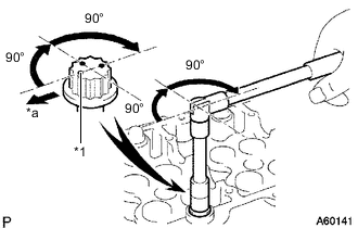
*1 Painted Mark *a Front Mark the front of each cylinder head bolt with paint.
-
Further tighten the cylinder head bolts by 90° in the sequence shown in the illustration above.
-
Tighten the cylinder head bolts by an additional 90°.
-
Check that the painted marks are now facing rearward.
-
-
INSTALL CAMSHAFT
-
INSTALL CYLINDER BLOCK INSULATOR
-
Install the cylinder block insulator to the cylinder head.
-
-
INSTALL NO. 2 TIMING BELT COVER
-
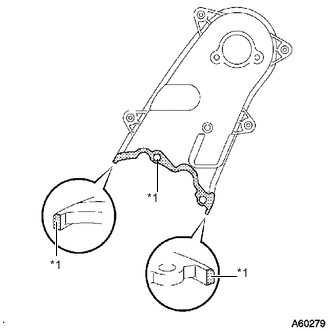
Text in Illustration *1 Seal Packing Apply seal packing (FIPG) to the specified areas shown in the illustration.
Seal packing Toyota Genuine Seal Packing Black, Three Bond 1207B or equivalent Note
After applying seal packing, install the No. 2 timing belt cover within 3 minutes and tighten the bolts and nut within 15 minutes.
-
Install the No. 2 timing belt cover with the 4 bolts and nut.
- Torque:
- 10 N*m { 102 kgf*cm, 7 ft.*lbf }
-
-
INSTALL CAMSHAFT TIMING PULLEY
-
Install the camshaft timing pulley.
-
Install the bolt of the camshaft timing pulley while holding the camshaft with a wrench.
- Torque:
- 98 N*m { 1000 kgf*cm, 72 ft.*lbf }
-
-
INSTALL NO. 1 TIMING BELT IDLER SUB-ASSEMBLY
-
INSTALL TIMING BELT
-
Install the timing belt Click here.
-
-
INSPECT AND ADJUST VALVE CLEARANCE
-
INSTALL INJECTOR ASSEMBLY
-
INSPECT FOR FUEL LEAK
-
INSTALL CYLINDER HEAD COVER SUB-ASSEMBLY
-
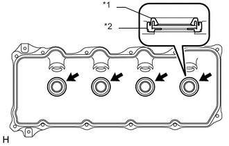
Text in Illustration *1 No. 3 Cylinder Head Cover Gasket *2 Cylinder Head Cover Install 4 new No. 3 cylinder head cover gaskets to the cylinder head cover in the directions shown in the illustration.
Note
-
Do not install the No. 3 cylinder head cover gaskets at an angle.
-
Check that there is no foreign matter at the installation location of the No. 3 cylinder head cover gaskets.
-
-
Remove any old seal packing (FIPG material) from the cylinder head.
-
Text in Illustration *1 Seal Packing Apply seal packing to the areas shown in the illustration.
Seal packing Toyota Genuine Seal Packing Black, Three Bond 1207B or equivalent Note
-
Remove any oil from the contact surface.
-
Install the cylinder head cover within 3 minutes after applying seal packing.
-
Do not start the engine for at least 2 hours after installation.
-
-
Install a new gasket and the cylinder head cover with the 10 bolts and 2 nuts.
- Torque:
- 9.0 N*m { 92 kgf*cm, 80 in.*lbf }
-
-
INSTALL NOZZLE HOLDER SEAL
-
Install 4 new nozzle holder seals.
-
-
INSTALL NO. 3 VACUUM TRANSMITTING PIPE SUB-ASSEMBLY
-
Install the No. 3 vacuum transmitting pipe with the bolt.
- Torque:
- 18 N*m { 184 kgf*cm, 13 ft.*lbf }
-
Connect the vacuum hose.
-
-
INSTALL NO. 2 CYLINDER HEAD COVER SUB-ASSEMBLY
-
INSTALL COMMON RAIL ASSEMBLY
-
INSTALL NO. 2 INTAKE MANIFOLD INSULATOR
-
INSTALL FUEL INLET PIPE SUB-ASSEMBLY
-
INSTALL GLOW PLUG ASSEMBLY
-
Install the glow plugs Click here.
-
-
INSTALL INTAKE MANIFOLD
-
Install the intake manifold Click here.
-
-
INSTALL EXHAUST MANIFOLD WITH TURBOCHARGER
-
Install the exhaust manifold with turbocharger Click here.
-
-
ADD ENGINE OIL
-
CONNECT CABLE TO NEGATIVE BATTERY TERMINAL
Note
When disconnecting the cable, some systems need to be initialized after the cable is reconnected Click here.
-
BLEED AIR FROM FUEL SYSTEM
-
ADD ENGINE COOLANT
-
INSPECT FOR COOLANT LEAK
-
INSPECT FOR OIL LEAK
-
INSPECT FOR FUEL LEAK
-
INSPECT ENGINE OIL LEVEL
-
INSTALL NO. 1 ENGINE UNDER COVER SUB-ASSEMBLY
-
INSTALL FRONT BUMPER LOWER COVER