CAMSHAFT INSTALLATION

CAUTION / NOTICE / HINT
Note
-
When replacing the injectors (including shuffling the injectors between the cylinders), common rail or cylinder head, it is necessary to replace the injection pipes with new ones.
-
When replacing the fuel supply pump, common rail, cylinder block, cylinder head, cylinder head gasket or timing gear case, it is necessary to replace the fuel inlet pipe with a new one.
PROCEDURE
-
INSTALL CAMSHAFT
-
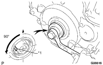
Text in Illustration *1 Key Using the crankshaft pulley bolt, set the No. 1 cylinder to 90° BTDC/compression.
Tech Tips
Set the No. 1 cylinder to 90° BTDC/compression to prevent the top of the piston from hitting against the valve head.
-
Install the camshaft.
-
Apply MP grease to the thrust portion of the camshaft.
-
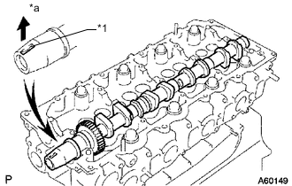
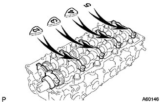
Place the camshaft on the cylinder head with the key groove facing upward.
Text in Illustration *1 Key Groove *a Upward -
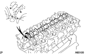
Align the timing marks (1 dot mark) of the camshaft drive and driven main gears, and set the No. 2 camshaft in place.
-
-
Remove any old seal packing (FIPG material) from the camshaft bearing cap.
-
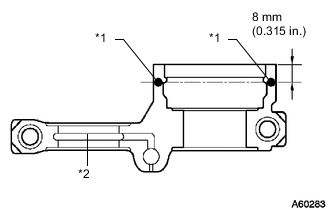
Apply seal packing to the specified areas shown in the illustration.
Text in Illustration *1 Seal Packing *2 Oil Passage Seal packing Toyota Genuine Seal Packing Black, Three Bond 1207B or equivalent Standard seal diameter 4 mm (0.157 in.) Note
-
Do not allow seal packing to contact the oil passage of the bearing cap.
-
After applying seal packing, install the camshaft bearing caps within 3 minutes and tighten the bolts within 15 minutes.
-
Do not start the engine for at least 2 hours after installation.
-
Install the 5 bearing caps to their proper locations.
-
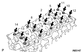
Apply a light coat of engine oil to the threads and under the heads of the bearing cap bolts.
-
Install and uniformly tighten the 15 bearing cap bolts in several passes in the sequence shown in the illustration.
- Torque:
- 19 N*m { 194 kgf*cm, 14 ft.*lbf }
-
-
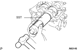
Install a new camshaft oil seal.
-
Apply MP grease to the lip of a new oil seal.
-
Using SST and a hammer, tap in the oil seal until its surface is flush with the surfaces of the camshaft bearing cap and cylinder head.
- SST
- 09608-06041
-
-
-
INSTALL NO. 2 TIMING BELT COVER
-
INSTALL CAMSHAFT TIMING PULLEY
-
INSTALL NO. 1 TIMING BELT IDLER SUB-ASSEMBLY
-
INSTALL TIMING BELT
-
INSPECT AND ADJUST VALVE CLEARANCE
-
INSTALL NO. 1 TIMING BELT COVER
-
INSTALL FAN SHROUD
-
INSTALL NO. 1 RADIATOR HOSE
-
INSTALL INJECTOR ASSEMBLY
-
INSPECT FOR FUEL LEAK
-
INSTALL CYLINDER HEAD COVER SUB-ASSEMBLY
-
INSTALL NOZZLE HOLDER SEAL
-
INSTALL VENTILATION PIPE
-
INSTALL NO. 2 CYLINDER HEAD COVER SUB-ASSEMBLY
-
INSTALL WIRE HARNESS
-
INSTALL NO. 2 NOZZLE LEAKAGE PIPE ASSEMBLY
-
INSTALL NO. 4 INJECTION PIPE SUB-ASSEMBLY
-
INSTALL MANIFOLD STAY WITH VACUUM SWITCHING VALVE
-
INSTALL INTAKE AIR CONNECTOR WITH DIESEL THROTTLE BODY ASSEMBLY (w/o EGR System)
-
CONNECT ENGINE WIRE (w/o EGR System)
-
INSTALL AIR CONNECTOR STAY (w/o EGR System)
-
INSTALL INJECTION PIPE (w/o EGR System)
-
INSTALL THROTTLE BODY BRACKET (w/o EGR System)
-
INSTALL NO. 2 EGR VALVE ASSEMBLY (w/ EGR System with EGR Cooler)
-
INSTALL EGR COOLER WITH PIPE (w/ EGR System with EGR Cooler)
-
TEMPORARILY INSTALL ELECTRIC EGR CONTROL VALVE ASSEMBLY (w/ EGR System with EGR Cooler)
-
TIGHTEN ELECTRIC EGR CONTROL VALVE ASSEMBLY (w/ EGR System with EGR Cooler)
-
INSTALL NO. 1 EGR PIPE SUB-ASSEMBLY (w/ EGR System without EGR Cooler)
-
TEMPORARILY INSTALL ELECTRIC EGR CONTROL VALVE ASSEMBLY (w/ EGR System without EGR Cooler)
-
TIGHTEN ELECTRIC EGR CONTROL VALVE ASSEMBLY (w/ EGR System without EGR Cooler)
-
INSTALL AIR CONNECTOR STAY (w/ EGR System)
-
INSTALL ELECTRIC VACUUM REGULATING VALVE ASSEMBLY (w/ EGR System)
-
INSTALL EGR VALVE BRACKET (w/ EGR System)
-
CONNECT ENGINE WIRE (for LHD)
-
CONNECT ENGINE WIRE (for RHD)
-
INSTALL INJECTION PIPE (w/ EGR System)
-
CONNECT NO. 4 WATER BY-PASS HOSE (w/ EGR System with EGR Cooler)
-
CONNECT NO. 3 WATER BY-PASS HOSE (w/ EGR System with EGR Cooler)
-
INSTALL DIESEL THROTTLE BODY ASSEMBLY (w/ EGR System)
-
INSTALL NO. 1 INTAKE PIPE
-
CONNECT NO. 4 VACUUM TRANSMITTING PIPE SUB-ASSEMBLY
-
CONNECT INLET HEATER WATER HOSE
-
INSTALL COWL TOP VENTILATOR LOUVER SUB-ASSEMBLY
-
CONNECT CABLE TO NEGATIVE BATTERY TERMINAL
Note
When disconnecting the cable, some systems need to be initialized after the cable is reconnected Click here.
-
BLEED AIR FROM FUEL SYSTEM
-
ADD ENGINE COOLANT
-
INSPECT FOR COOLANT LEAK
-
INSPECT FOR OIL LEAK
-
INSPECT FOR FUEL LEAK
-
INSTALL NO. 1 ENGINE UNDER COVER SUB-ASSEMBLY
-
INSTALL FRONT BUMPER LOWER COVER
-
INSPECT ENGINE OIL LEVEL