VALVE CLEARANCE ADJUSTMENT
CAUTION / NOTICE / HINT
Note
-
When replacing the injectors (including shuffling the injectors between the cylinders), common rail or cylinder head, it is necessary to replace the injection pipes with new ones.
-
When replacing the fuel supply pump, common rail, cylinder block, cylinder head, cylinder head gasket or timing gear case, it is necessary to replace the fuel inlet pipe with a new one.
Tech Tips
The injectors do not need to be removed when inspecting the valve clearance.
PROCEDURE
-
REMOVE CYLINDER HEAD COVER SUB-ASSEMBLY
-
SET NO. 1 CYLINDER TO TDC/COMPRESSION
-
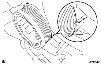
Text in Illustration *1 Matchmark Align the matchmarks of the crankshaft pulley and timing gear case cover by rotating the crankshaft clockwise.
Tech Tips
Make sure that both cam lobes (intake side and exhaust side) of the No. 1 cylinder face upward.
-
-
INSPECT VALVE CLEARANCE
-
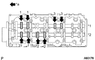
Text in Illustration *1 Exhaust *2 Intake *a Front Check only the valves indicated.
-
Using a feeler gauge, measure the clearance between the valve lifter and camshaft.
Standard Valve Clearance (Cold) Item Specified Condition Intake 0.2 to 0.3 mm (0.00787 to 0.0118 in.) Exhaust 0.35 to 0.45 mm (0.0138 to 0.0177 in.) Write down any valve clearance measurements that are not within the specified range. These measurements will be used later to determine the size of the adjustment lifter to be installed.
-
-
Turn the crankshaft 360° to set the No. 4 cylinder to TDC/compression.
-
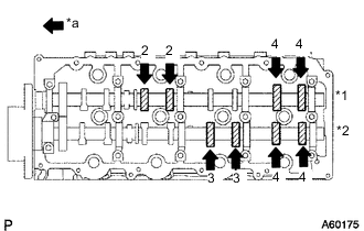
Text in Illustration *1 Exhaust *2 Intake *a Front Check only the valves indicated.
-
Using a feeler gauge, measure the clearance between the valve lifter and camshaft.
Standard Valve Clearance (Cold) Item Specified Condition Intake 0.2 to 0.3 mm (0.00787 to 0.0118 in.) Exhaust 0.35 to 0.45 mm (0.0138 to 0.0177 in.) Write down valve clearance measurements that are not within the specified range. These measurements will be used later to determine the size of the adjustment lifter to be installed.
-
-
-
ADJUST VALVE CLEARANCE
-
Remove the camshafts Click here.
-
Remove the valve lifters.
-
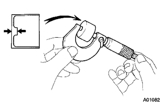
Using a micrometer, measure the thickness of the removed lifter.
-
Calculate the thickness of a new lifter so that the valve clearance is within the specified range.
A B C New lifter thickness Used lifter thickness Measured valve clearance New lifter thickness Intake: A = B + (C - 0.25 mm (0.00984 in.)) Exhaust: A = B + (C - 0.40 mm (0.0157 in.)) -
Select a new lifter with a thickness as close as possible to the calculated values.
Tech Tips
Valve lifters are available in 35 sizes in increments of 0.02 mm (0.000787 in.), from 5.06 mm (0.199 in.) to 5.74 mm (0.226 in.).
-
Install the selected valve lifter.
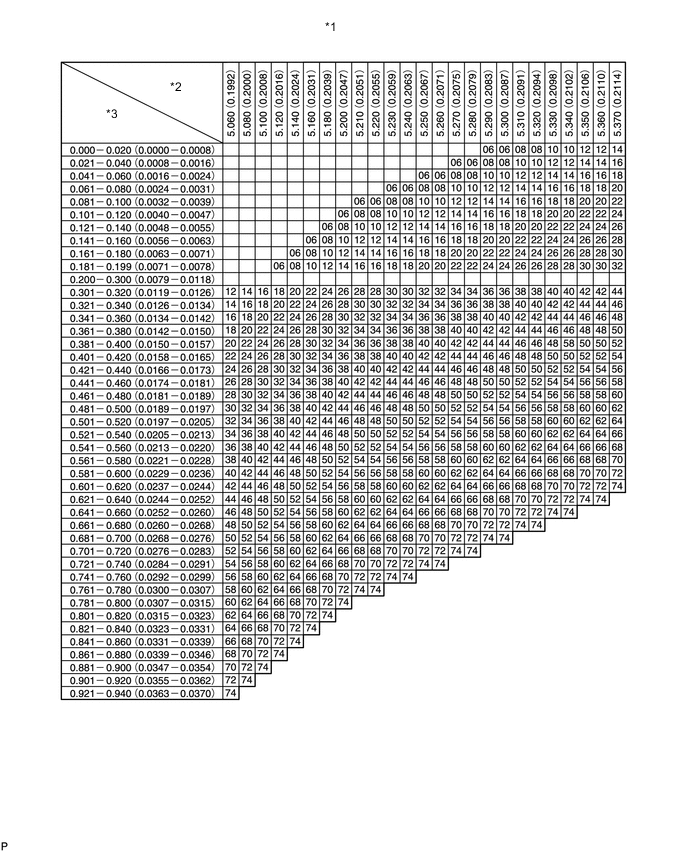
Text in Illustration *1 Valve Lifter Selection Chart (Intake) *2 Installed lifter thickness mm (in.) *3 Measured clearance mm (in.) - - 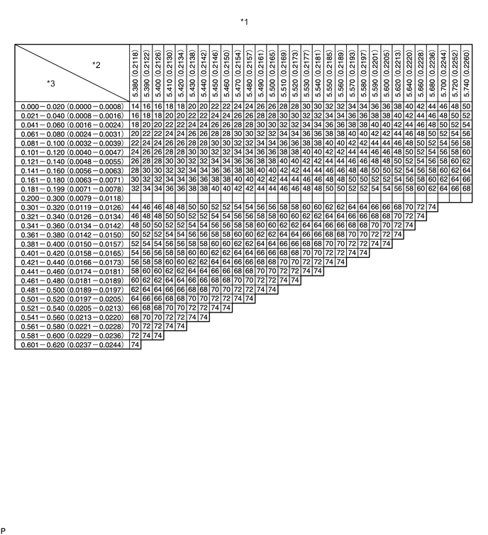
Text in Illustration *1 Valve Lifter Selection Chart (Intake) *2 Installed lifter thickness mm (in.) *3 Measured clearance mm (in.) - - Standard intake valve clearance (Cold) 0.2 to 0.3 mm (0.00787 to 0.0118 in.) EXAMPLE A 5.25 mm (0.207 in.) lifter is installed, and the measured clearance is 0.4 mm (0.0157 in.). Replace the 5.25 mm (0.207 in.) lifter with a No. 40 lifter. New Lifter Thickness Lifter No. Specified Condition Lifter No. Specified Condition Lifter No. Specified Condition 06 5.06 mm (0.1992 in.) 30 5.30 mm (0.2087 in.) 54 5.54 mm (0.2181 in.) 08 5.08 mm (0.2000 in.) 32 5.32 mm (0.2094 in.) 56 5.56 mm (0.2189 in.) 10 5.10 mm (0.2008 in.) 34 5.34 mm (0.2102 in.) 58 5.58 mm (0.2197 in.) 12 5.12 mm (0.2016 in.) 36 5.36 mm (0.2110 in.) 60 5.60 mm (0.2205 in.) 14 5.14 mm (0.2024 in.) 38 5.38 mm (0.2118 in.) 62 5.62 mm (0.2213 in.) 16 5.16 mm (0.2031 in.) 40 5.40 mm (0.2126 in.) 64 5.64 mm (0.2220 in.) 18 5.18 mm (0.2039 in.) 42 5.42 mm (0.2134 in.) 66 5.66 mm (0.2228 in.) 20 5.20 mm (0.2047 in.) 44 5.44 mm (0.2142 in.) 68 5.68 mm (0.2236 in.) 22 5.22 mm (0.2055 in.) 46 5.46 mm (0.2150 in.) 70 5.70 mm (0.2244 in.) 24 5.24 mm (0.2063 in.) 48 5.48 mm (0.2157 in.) 72 5.72 mm (0.2252 in.) 26 5.26 mm (0.2071 in.) 50 5.50 mm (0.2165 in.) 74 5.74 mm (0.2260 in.) 28 5.28 mm (0.2079 in.) 52 5.52 mm (0.2173 in.) - - 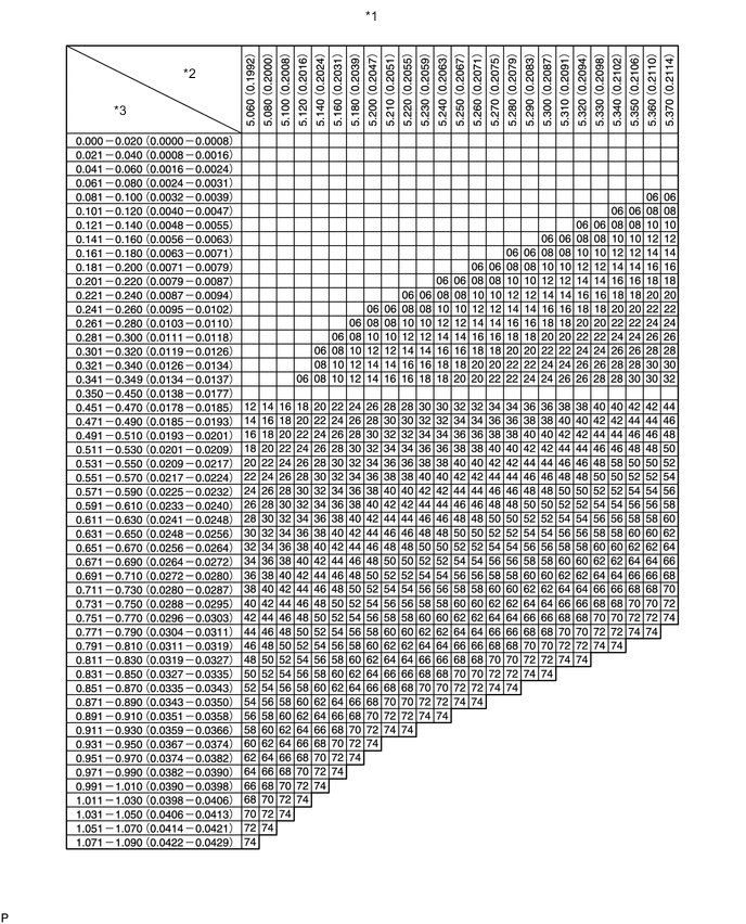
Text in Illustration *1 Valve Lifter Selection Chart (Exhaust) *2 Installed lifter thickness mm (in.) *3 Measured clearance mm (in.) - - 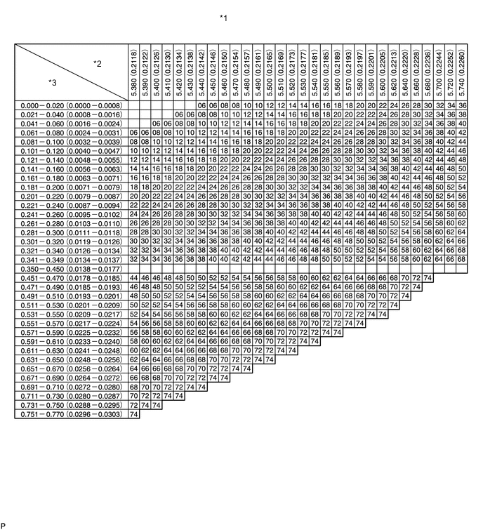
Text in Illustration *1 Valve Lifter Selection Chart (Exhaust) *2 Installed lifter thickness mm (in.) *3 Measured clearance mm (in.) - - Standard exhaust valve clearance (Cold) 0.35 to 0.45 mm (0.0138 to 0.0177 in.) EXAMPLE A 5.34 mm (0.210 in.) lifter is installed, and the measured clearance is 0.48 mm (0.0189 in.). Replace the 5.34 mm (0.210 in.) lifter with a No. 42 lifter. New Lifter Thickness Lifter No. Specified Condition Lifter No. Specified Condition Lifter No. Specified Condition 06 5.06 mm (0.1992 in.) 30 5.30 mm (0.2087 in.) 54 5.54 mm (0.2181 in.) 08 5.08 mm (0.2000 in.) 32 5.32 mm (0.2094 in.) 56 5.56 mm (0.2189 in.) 10 5.10 mm (0.2008 in.) 34 5.34 mm (0.2102 in.) 58 5.58 mm (0.2197 in.) 12 5.12 mm (0.2016 in.) 36 5.36 mm (0.2110 in.) 60 5.60 mm (0.2205 in.) 14 5.14 mm (0.2024 in.) 38 5.38 mm (0.2118 in.) 62 5.62 mm (0.2213 in.) 16 5.16 mm (0.2031 in.) 40 5.40 mm (0.2126 in.) 64 5.64 mm (0.2220 in.) 18 5.18 mm (0.2039 in.) 42 5.42 mm (0.2134 in.) 66 5.66 mm (0.2228 in.) 20 5.20 mm (0.2047 in.) 44 5.44 mm (0.2142 in.) 68 5.68 mm (0.2236 in.) 22 5.22 mm (0.2055 in.) 46 5.46 mm (0.2150 in.) 70 5.70 mm (0.2244 in.) 24 5.24 mm (0.2063 in.) 48 5.48 mm (0.2157 in.) 72 5.72 mm (0.2252 in.) 26 5.26 mm (0.2071 in.) 50 5.50 mm (0.2165 in.) 74 5.74 mm (0.2260 in.) 28 5.28 mm (0.2079 in.) 52 5.52 mm (0.2173 in.) - - -
Install the camshafts Click here.
-
-
INSPECT FOR COOLANT LEAK
-
BLEED AIR FROM FUEL SYSTEM
-
INSPECT FOR FUEL LEAK
-
INSPECT FOR OIL LEAK