CYLINDER BLOCK REASSEMBLY

PROCEDURE
-
INSTALL STUD BOLT
Tech Tips
If a stud bolt is deformed or the threads are damaged, replace it.
-
Install the stud bolts.
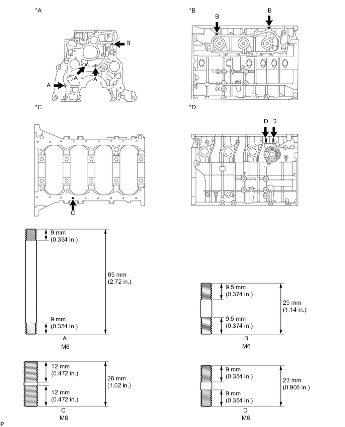
Text in Illustration *A for Front Side *B for Left Side *C for Oil Pan Side *D for Right Side
-
-
INSTALL NO. 1 OIL NOZZLE SUB-ASSEMBLY
-
Align the pin of the No. 1 oil nozzle with the pin hole of the cylinder block.
-
Install the 4 No. 1 oil nozzles with the 4 check valves.
- Torque:
- 26 N*m { 265 kgf*cm, 19 ft.*lbf }
-
-
INSTALL PISTON WITH PIN SUB-ASSEMBLY
-
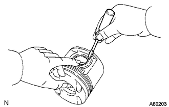
Using a small screwdriver, install a new snap ring on one side of the piston pin hole.
-
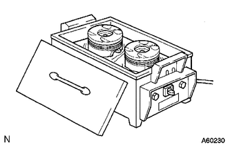
Gradually heat the piston to approximately 80°C (176°F).
-
Coat the piston pin with engine oil.
-
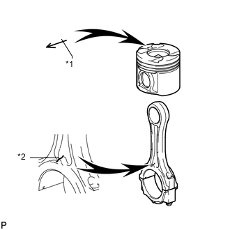
Text in Illustration *1 Front Mark (Arrow) *2 Front Mark (Protrusion) Align the front marks of the piston and connecting rod, connect the connecting rod to the piston, and then push in the piston pin with your thumb.
-
Check the fit between the piston and piston pin. Try to move the piston back and forth on the piston pin.
-
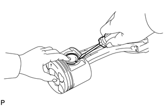
Using a small screwdriver, install a new snap ring on the other side of the piston pin hole.
-
-
INSTALL PISTON RING SET
-
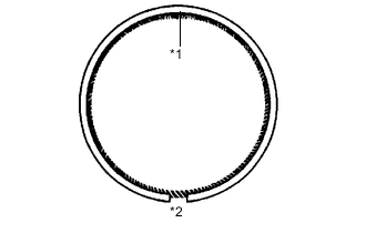
Text in Illustration *1 Coil Joint *2 Oil Ring End Install the coil and oil ring by hand.
Tech Tips
Make sure the end gap of the oil ring and the coil joint are on opposite sides.
-
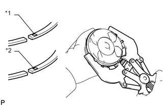
Text in Illustration *1 No. 1 *2 No. 2 Using a piston ring expander, install the No. 1 and No. 2 piston rings with the code marks facing upward.
Code Mark Ring Code Mark No. 1 NAA or NAC No. 2 N or KD1 -
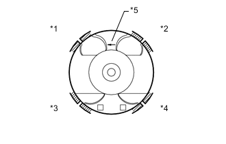
Text in Illustration *1 No. 1 Piston Ring *2 Oil Ring *3 Coil *4 No. 2 Piston Ring *5 Front Mark (Arrow) Position the piston rings so that the ring ends are as shown in the illustration.
Note
Do not align the ring ends.
-
-
INSTALL CRANKSHAFT BEARING
Tech Tips
Upper bearings have an oil groove and oil hole. Lower bearings do not.
-
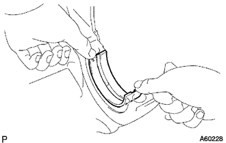
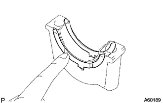
Align the bearing claw with the claw groove of the cylinder block and push in the 5 upper bearings.
-
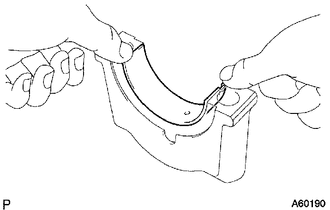
Align the bearing claw with the claw groove of the crankshaft bearing cap and push in the 5 lower bearings.
-
-
INSTALL CRANKSHAFT
-
Place the crankshaft on the cylinder block.
-
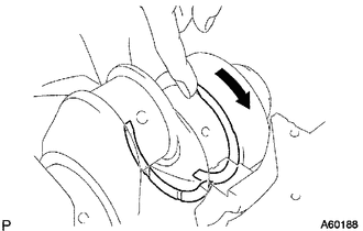
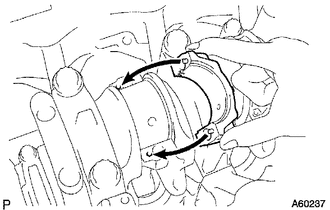
Push the crankshaft in one direction and install one thrust washer to the No. 5 journal position with the oil groove facing outward.
-
Push the crankshaft in the opposite direction and install the other thrust washer to the No. 5 journal position with the oil groove facing outward.
-
Install the 2 thrust washers to the No. 5 bearing cap with the grooves facing outward.
-
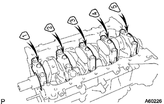
Install the 5 crankshaft bearing caps to their proper locations.
-
Install the crankshaft bearing cap bolts.
Tech Tips
-
The crankshaft bearing cap bolts are tightened in 2 progressive steps.
-
If a crankshaft bearing cap bolt is broken or deformed, replace it.
-
Apply a light coat of engine oil to the threads and under the bolt heads of the crankshaft bearing cap bolts.
-
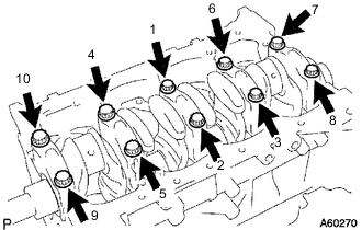
Install and uniformly tighten the 10 bolts of the crankshaft bearing caps in several passes in the sequence shown in the illustration.
- Torque:
- 50 N*m { 510 kgf*cm, 37 ft.*lbf }
If any one of the bearing cap bolts does not meet the torque specification, replace the bearing cap bolt.
-
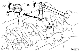
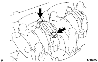
Text in Illustration *1 Painted Mark *a Front Mark the front of each crankshaft bearing cap bolt with paint.
-
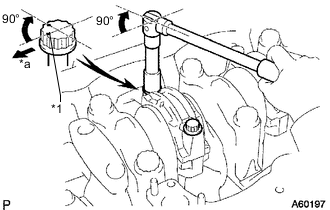
Tighten the crankshaft bearing cap bolts by 90° in the numerical order shown in the previous illustration.
-
Check that the painted marks are now at a 90° angle to the front.
-
-
Check that the crankshaft turns smoothly.
-
Check the crankshaft thrust clearance.
-
-
INSTALL CONNECTING ROD BEARING
-
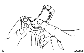
Align the bearing claw with the groove of the connecting rod or connecting rod cap.
-
Install the bearings to the connecting rod and connecting rod cap.
-
-
INSPECT CRANKSHAFT THRUST CLEARANCE
-
INSTALL PISTON AND CONNECTING ROD
-
Apply engine oil to the cylinder walls, pistons and the surfaces of the connecting rod bearings.
-
Check the positions of the piston ring ends.
-
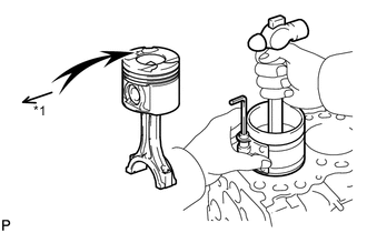
Text in Illustration *1 Front Mark (Arrow) Using a piston ring compressor, push the correctly numbered piston and connecting rod assembly into the cylinder with the front mark of the piston facing forward.
-
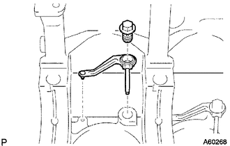
Place the connecting rod cap on the connecting rod.
-
Match each numbered connecting rod cap with the correct connecting rod.
-
Align the pins of the connecting rod cap with the pin holes of the connecting rod and install the connecting rod cap.
-
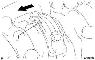
Text in Illustration *1 Front Mark (Protrusion) 
Front Check that the front mark of the connecting rod cap is facing forward.
-
-
Install the connecting rod cap bolts.
Tech Tips
-
The connecting rod cap bolts are tightened in 2 progressive steps.
-
If any connecting rod bolt is broken or deformed, replace it.
-
Apply a light coat of engine oil to the threads and under the heads of the connecting rod cap bolts.
-
Install and alternately tighten the bolts of the connecting rod cap in several passes.
- Torque:
- 35 N*m { 357 kgf*cm, 26 ft.*lbf }
Tech Tips
If any one of the connecting rod cap bolts does not meet the torque specification, replace the cap bolt.
-
Text in Illustration *1 Painted Mark *a Front Mark the front of each connecting rod cap bolt with paint.
-
Tighten the connecting rod cap bolts by 90° as shown in the illustration.
-
Check that the painted marks are now at a 90° angle to the front.
-
-
Check that the crankshaft turns smoothly.
-
-
INSPECT CONNECTING ROD THRUST CLEARANCE
-
INSTALL CYLINDER BLOCK OIL ORIFICE