CYLINDER BLOCK INSPECTION

CAUTION / NOTICE / HINT
Tech Tips
-
Any digits beyond the 1/100 mm (1/1000 in.) place for standard, minimum and maximum values should be used as a reference only.
-
When both standard and maximum or minimum values are listed for an inspection, use the standard value as a reference only and base any judgments on the maximum and minimum values.
PROCEDURE
-
INSPECT CYLINDER BLOCK OIL ORIFICE
-
Check the oil orifice for damage or clogging.
If necessary, replace the cylinder block oil orifice.
-
-
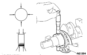
INSPECT OIL CHECK VALVE SUB-ASSEMBLY
-
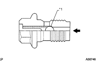
Text in Illustration *1 Ball 
Push Push the ball of the oil check valve with a wooden stick to check if it is stuck.
If the ball of the oil check valve is stuck, replace the oil check valve sub-assembly.
-
-
INSPECT NO. 1 OIL NOZZLE SUB-ASSEMBLY
-
Check the No. 1 oil nozzle for damage or clogging.
If necessary, replace the No. 1 oil nozzle sub-assembly.
-
-
CLEAN CYLINDER BLOCK SUB-ASSEMBLY
-
Using a gasket scraper, remove all the gasket material from the top surface of the cylinder block.
-
Using a soft brush and solvent, thoroughly clean the cylinder block sub-assembly.
-
-
INSPECT CYLINDER BLOCK FOR WARPAGE
-
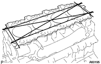
Inspect for warpage.
-
Using a precision straightedge and feeler gauge, measure the surface of the cylinder block that contacts the cylinder head for warpage.
Maximum warpage 0.1 mm (0.00394 in.) If the warpage is more than the maximum, replace the cylinder block sub-assembly.
-
-
Visually check the cylinders for vertical scratches.
If deep scratches are present, rebore all 4 cylinders. If necessary, replace the cylinder block.
-
-
INSPECT CYLINDER BORE
-
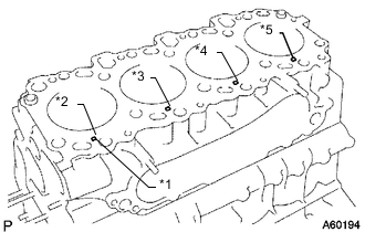
Text in Illustration *1 Mark 1, 2 or 3 *2 No. 1 *3 No. 2 *4 No. 3 *5 No. 4 Inspect the cylinder bore diameter.
Tech Tips
There are 3 standard cylinder bore diameter sizes, marked 1, 2 and 3 accordingly. The mark is stamped on the cylinder block.
-
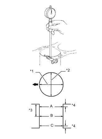
Text in Illustration *1 Axial Direction *2 Thrust Direction *3 Center *4 10 mm (0.394 in.) Front 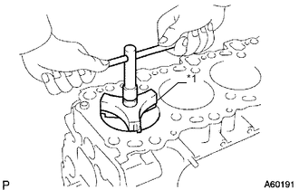
Text in Illustration *1 Ridge Reamer Using a cylinder gauge, measure the cylinder bore diameter at positions A, B and C in the thrust and axial directions.
Standard Diameter Item Specified Condition STD Mark 1 96.00 to 96.01 mm (3.7795 to 3.7799 in.) STD Mark 2 96.01 to 96.02 mm (3.7799 to 3.7803 in.) STD Mark 3 96.02 to 96.03 mm (3.7803 to 3.7807 in.) O/S 0.50 96.50 to 96.53 mm (3.7992 to 3.8004 in.) O/S 0.75 96.75 to 96.78 mm (3.8090 to 3.8102 in.) O/S 1.00 97.00 to 97.03 mm (3.8189 to 3.8201 in.) Maximum Diameter Item Specified Condition STD 96.23 mm (3.7886 in.) O/S 0.50 96.73 mm (3.8083 in.) O/S 0.75 96.98 mm (3.8181 in.) O/S 1.00 97.23 mm (3.8280 in.) If the diameter is more than the maximum, rebore all 4 cylinders. If necessary, replace the cylinder block sub-assembly.
If the wear is less than 0.2 mm (0.00787 in.), using a ridge reamer, grind the top of the cylinder.
-
-
-
CLEAN PISTON
-
Using a groove cleaning tool or broken ring, clean the piston ring grooves.
-
Using solvent and a brush, thoroughly clean the piston.
Note
Do not use a wire brush.
-
-
INSPECT PISTON DIAMETER
Tech Tips
When replacing the piston with pin sub-assembly with a supply part, there are a number of piston diameter size to choose from, but there is only one size of piston pin diameter.
-
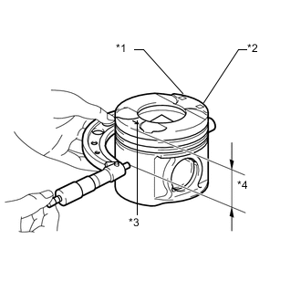
Text in Illustration *1 Size Mark *2 Piston Pin Hole Inside Diameter Mark *3 Front Mark (Arrow) *4 Distance Using a micrometer, measure the piston diameter according to the following conditions: 1) measure at a right angle to the piston center line, and 2) measure at the indicated distance from the piston head.
Standard Distance 65.00 to 65.06 mm (2.5590 to 2.5593 in.) Standard Piston Diameter Item Specified Condition STD Mark 1 95.92 to 95.93 mm (3.7764 to 3.7768 in.) STD Mark 2 95.93 to 95.94 mm (3.7768 to 3.7772 in.) STD Mark 3 95.94 to 95.95 mm (3.7772 to 3.7776 in.) STD O/S 0.50 96.42 to 96.45 mm (3.7960 to 3.7972 in.) STD O/S 0.75 96.67 to 96.70 mm (3.8059 to 3.8070 in.) STD O/S 1.00 96.92 to 96.95 mm (3.8157 to 3.8169 in.) -
Using a micrometer, measure the piston pin diameter.
Standard Piston Pin Diameter Item Specified Condition Mark A 34.000 to 34.004 mm (1.3386 to 1.3387 in.) Mark B 34.004 to 34.008 mm (1.3387 to 1.3389 in.) Mark C 34.008 to 34.009 mm (1.3389 to 1.3391 in.) -
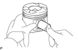
Inspect the piston pin fit.
-
At 80°C (176°F), check that the piston pin can be pushed into the piston pin hole with your thumb.
If the pin can be installed at a lower temperature, replace the piston with pin sub-assembly.
-
-
-
INSPECT PISTON OIL CLEARANCE
-
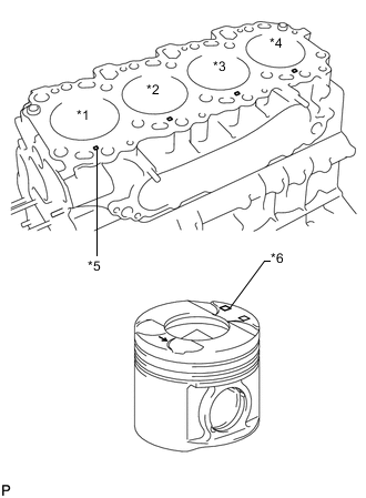
Text in Illustration *1 No. 1 *2 No. 2 *3 No. 3 *4 No. 4 *5 Mark 1, 2 or 3 *6 Size Mark Measure the cylinder bore diameter in the thrust direction.
-
Subtract the piston diameter measurement from the cylinder bore diameter measurement.
Standard oil clearance 0.07 to 0.09 mm (0.00276 to 0.00354 in.) Maximum oil clearance 0.14 mm (0.00551 in.) If the oil clearance is more than the maximum, replace all 4 pistons and rebore all 4 cylinders.
If necessary, replace the cylinder block sub-assembly.
Tech Tips
When the cylinder block is replaced, use a piston with the same number mark as the cylinder diameter marked on the new cylinder block.
-
-
INSPECT RING GROOVE CLEARANCE
-
Using a feeler gauge, measure the clearance between a new piston ring and the wall of the ring groove.
Standard Groove Clearance Item Specified Condition No. 2 piston ring 0.090 to 0.135 mm (0.00354 to 0.00531 in.) Oil ring 0.030 to 0.075 mm (0.00118 to 0.00295 in.) If the result is not as specified, replace the piston with pin sub-assembly.
-
-
INSPECT PISTON RING END GAP
-
Insert the piston ring into the cylinder bore.
-
Using a piston, push the piston ring a little beyond the bottom of the ring travel, 120 mm (4.72 in.) from the top of the cylinder block.
-
Using a feeler gauge, measure the end gap.
Standard End Gap Item Specified Condition No. 1 piston ring 0.27 to 0.39 mm (0.0106 to 0.0154 in.) No. 2 piston ring 0.55 to 0.70 mm (0.0217 to 0.0276 in.) Oil ring 0.20 to 0.40 mm (0.00787 to 0.0157 in.) Maximum End Gap Item Specified Condition No. 1 piston ring 0.85 mm (0.0335 in.) No. 2 piston ring 1.07 mm (0.0421 in.) Oil ring 0.77 mm (0.0303 in.) If the end gap is more than the maximum, replace the piston ring.
If the end gap is more than the maximum even with a new piston ring, rebore all 4 cylinders or replace the cylinder block sub-assembly.
-
-
INSPECT PISTON PIN OIL CLEARANCE
Tech Tips
When replacing the piston with pin sub-assembly with a supply part, there are a number of piston diameter size to choose from, but there is only one size of piston pin diameter.
-
Text in Illustration *1 Connecting Rod Bush Inside Diameter Mark A, B or C *2 Front Mark Using a caliper gauge, measure the inside diameter of the connecting rod bush.
Standard Bush Inside Diameter Item Specified Condition Mark A 34.012 to 34.016 mm (1.3390 to 1.3392 in.) Mark B 34.016 to 34.020 mm (1.3392 to 1.3393 in.) Mark C 34.020 to 34.024 mm (1.3393 to 1.3395 in.) -
Subtract the piston pin diameter measurement from the bush inside diameter measurement.
Standard oil clearance 0.008 to 0.016 mm (0.000315 to 0.000630 in.) Maximum oil clearance 0.03 mm (0.0113 in.) If the oil clearance is more than the maximum, replace the connecting rod sub-assembly.
If necessary, replace the piston with pin sub-assembly.
-
-
INSPECT CONNECTING ROD SUB-ASSEMBLY
-
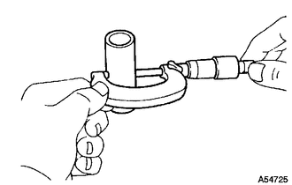
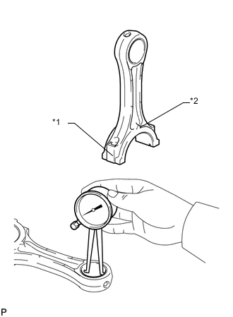
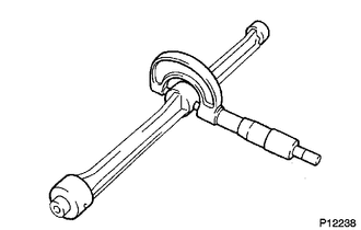
Using a rod aligner and feeler gauge, check the connecting rod alignment.
-
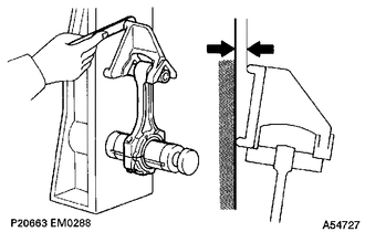
Check if the connecting rod is bent.
Maximum bend 0.03 mm (0.00118 in.) per 100 mm (3.94 in.) If the bend is more than the maximum, replace the connecting rod sub-assembly.
-
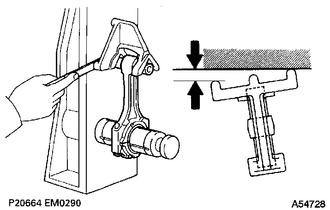
Check if the connecting rod is twisted.
Maximum twist 0.15 mm (0.00591 in.) per 100 mm (3.94 in.) If the twist is more than the maximum, replace the connecting rod sub-assembly.
-
-
-
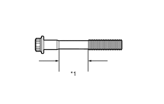
INSPECT CONNECTING ROD BOLT
-
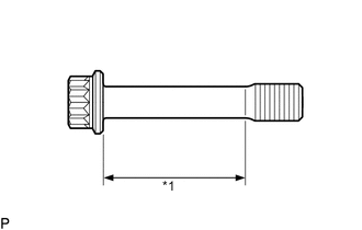
Text in Illustration *1 Tension Portion Using a vernier caliper, measure the diameter of the tension portion of the bolt.
Standard diameter 8.5 to 8.6 mm (0.335 to 0.339 in.) Minimum diameter 8.3 mm (0.327 in.) If the diameter is less than the minimum, replace the connecting rod bolt.
-
-
INSPECT NO. 1 BALANCESHAFT SUB-ASSEMBLY
-
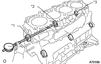
Using a cylinder gauge, measure the inside diameter of the balanceshaft bearing.
Standard Bearing Inside Diameter Item Specified Condition No. 1 42.000 to 42.020 mm (1.6535 to 1.6543 in.) No. 2 41.000 to 41.020 mm (1.6142 to 1.6150 in.) No. 3 32.000 to 32.020 mm (1.2598 to 1.2606 in.) Text in Illustration *1 No. 1 *2 No. 2 *3 No. 3 -
Using a micrometer, measure the outside diameter of the balanceshaft main journals.
Standard Main Journal Diameter Item Specified Condition No. 1 41.941 to 41.960 mm (1.6512 to 1.6520 in.) No. 2 40.931 to 40.950 mm (1.6115 to 1.6122 in.) No. 3 31.941 to 31.960 mm (1.2575 to 1.2583 in.) -
Subtract the outside diameter of the balanceshaft main journal from the inside diameter of the balanceshaft bearing.
Standard Clearance Item Specified Condition No. 1 0.040 to 0.079 mm (0.00157 to 0.00311 in.) No. 2 0.050 to 0.089 mm (0.00197 to 0.00350 in.) No. 3 0.040 to 0.079 mm (0.00157 to 0.00311 in.) Maximum Clearance Item Specified Condition No. 1 0.18 mm (0.00709 in.) No. 2 0.19 mm (0.00748 in.) No. 3 0.18 mm (0.00709 in.) If the clearance is more than the maximum, replace the cylinder block sub-assembly and No. 1 balanceshaft sub-assembly.
-
-
INSPECT NO. 2 BALANCESHAFT SUB-ASSEMBLY
-
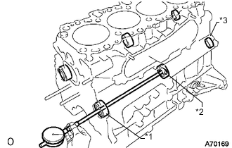
Text in Illustration *1 No. 1 *2 No. 2 *3 No. 3 Using a cylinder gauge, measure the inside diameter of the balanceshaft bearing.
Standard Bearing Inside Diameter Item Specified Condition No. 1 42.000 to 42.020 mm (1.6535 to 1.6543 in.) No. 2 41.000 to 41.020 mm (1.6142 to 1.6150 in.) No. 3 32.000 to 32.020 mm (1.2598 to 1.2606 in.) -
Using a micrometer, measure the outside diameter of the balanceshaft main journals.
Standard Main Journal Diameter Item Specified Condition No. 1 41.941 to 41.960 mm (1.6512 to 1.6520 in.) No. 2 40.931 to 40.950 mm (1.6115 to 1.6122 in.) No. 3 31.941 to 31.960 mm (1.2575 to 1.2583 in.) -
Subtract the outside diameter of the balanceshaft main journal from the inside diameter of the balanceshaft bearing.
Standard Clearance Item Specified Condition No. 1 0.040 to 0.079 mm (0.00157 to 0.00311 in.) No. 2 0.050 to 0.089 mm (0.00197 to 0.00350 in.) No. 3 0.040 to 0.079 mm (0.00157 to 0.00311 in.) Maximum Clearance Item Specified Condition No. 1 0.18 mm (0.00709 in.) No. 2 0.19 mm (0.00748 in.) No. 3 0.18 mm (0.00709 in.) If the clearance is more than the maximum, replace the cylinder block sub-assembly and No. 2 balanceshaft sub-assembly.
-
-
INSPECT CRANKSHAFT
-
Inspect for circle runout.
-
Place the crankshaft on V-blocks.
-
Using a dial indicator, measure the circle runout at the center journal.
Maximum circle runout 0.03 mm (0.00118 in.) If the circle runout is more than the maximum, replace the crankshaft.
-
-
Inspect the main journals and crank pins.
-
Using a micrometer, measure the diameter of each main journal and crank pin.
Standard Main Journal Diameter Item Specified Condition Mark 1 69.994 to 70.000 mm (2.7557 to 2.7559 in.) Mark 2 69.988 to 69.994 mm (2.7554 to 2.7557 in.) Mark 3 69.982 to 69.988 mm (2.7552 to 2.7554 in.) U/S 0.25 69.745 to 69.755 mm (2.7459 to 2.7463 in.) U/S 0.50 69.495 to 69.505 mm (2.7360 to 2.7364 in.) Standard Crank Pin Diameter Item Specified Condition Mark 1 58.994 to 59.000 mm (2.3226 to 2.3228 in.) Mark 2 58.988 to 58.994 mm (2.3224 to 2.3226 in.) Mark 3 58.982 to 58.988 mm (2.3221 to 2.3224 in.) U/S 0.25 58.745 to 58.755 mm (2.3128 to 2.3132 in.) U/S 0.50 58.495 to 58.505 mm (2.3029 to 2.3033 in.) If the diameter is not as specified, check the connecting rod oil clearance (See page ) and crankshaft oil clearance Click here. If necessary, grind or replace the crankshaft.
-
Check each main journal and crank pin for taper and out-of-round as shown in the illustration.
Maximum taper and out-of-round 0.02 mm (0.000787 in.) If the taper and out-of-round is more than the maximum, replace the crankshaft.
-
-
If necessary, grind and hone the main journals and/or crank pins.
-
Grind and hone the main journals and/or crank pins to the finished undersized diameter (refer to the procedures above).
-
Install new main journal and/or crank pin undersized bearings.
-
-
-
INSPECT CRANKSHAFT BEARING CAP SET BOLT
-
Text in Illustration *1 Measuring Area Using a vernier caliper, measure the diameter of the crankshaft bearing cap set bolt in the measuring area.
Standard diameter 13.5 to 14.0 mm (0.531 to 0.551 in.) Minimum diameter 12.6 mm (0.496 in.) If the diameter is less than the minimum, replace the crankshaft bearing cap set bolt.
-