CYLINDER HEAD GASKET INSTALLATION
CAUTION / NOTICE / HINT
Tech Tips
for Automatic Transmission:
Perform "Inspection After Repairs" after replacing the cylinder head sub-assembly or cylinder head LH Click here.
PROCEDURE
-
INSPECT CYLINDER HEAD SET BOLT
-
INSPECT CYLINDER HEAD SUB-ASSEMBLY
-
INSTALL CYLINDER HEAD GASKET
-
Remove any old packing (FIPG) material and be careful not to drop any oil on the contact surfaces of the cylinder head or cylinder block.
-
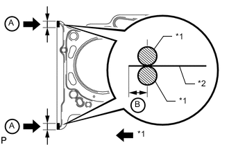
Text in Illustration *1 Seal Packing *2 Gasket Apply seal packing to a new cylinder head gasket as shown in the illustration.
Seal packing Toyota Genuine Seal Packing Black, Three Bond 1207B or equivalent Standard seal diameter 2.5 to 3.0 mm (0.0984 to 0.118 in.) Seal Packing Application Range A 10 to 15 mm (0.394 to 0.591 in.) B 1.25 to 1.5 mm (0.0492 to 0.0591 in.) Note
-
Remove any oil from the contact surface.
-
Install the cylinder head gasket within 3 minutes and tighten the bolts within 15 minutes after applying seal packing.
-
Do not add engine oil within 2 hours of installation.
-
-
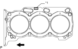
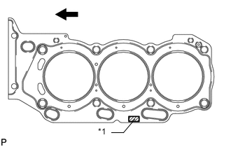
Text in Illustration *1 Lot No. 
Engine Front Place the cylinder head gasket on the cylinder block surface with the front face of the Lot No. stamp upward.
Note
Make sure that the gasket is installed facing the proper direction.
-
-
INSTALL CYLINDER HEAD SUB-ASSEMBLY
Tech Tips
for Automatic Transmission:
Perform "Inspection After Repairs" after replacing the cylinder head sub-assembly Click here.
-
Place the cylinder head on the cylinder block.
Note
-
Gently place the cylinder head in order not to damage the gasket with the bottom part of the head.
-
Make sure that no oil is on the mounting surface of the cylinder head.
Tech Tips
The cylinder head bolts are tightened in 3 progressive steps.
-
-
Apply a light coat of engine oil to the threads and under the heads of the cylinder head bolts.
-
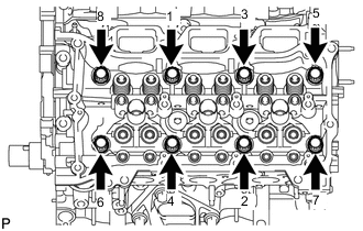
Step 1:
-
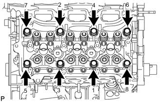
Using a 10 mm bi-hexagon wrench, install and uniformly tighten the 8 cylinder head bolts with the plate washers in several steps in the sequence shown in the illustration.
- Torque:
- 36 N*m { 367 kgf*cm, 27 ft.*lbf }
-
-
Step 2:
-
Mark the front side of each cylinder head bolt head with paint.
-
Tighten the cylinder head bolts another 90°.
-
-
Step 3:
-
Tighten the cylinder head bolts an additional 90°.
-
Check that the paint mark is now at a 180° angle to the front.
Note
Thoroughly wipe clean any seal packing.
-
-
-
INSTALL NO. 2 CYLINDER HEAD GASKET
-
Remove any old packing (FIPG) material and be careful not to drop any oil on the contact surfaces of the cylinder head or cylinder block.
-
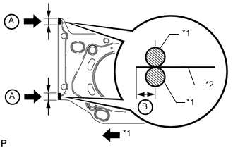
Text in Illustration *1 Seal Packing *2 Gasket Apply seal packing to a new cylinder head gasket as shown in the illustration.
Seal packing Toyota Genuine Seal Packing Black, Three Bond 1207B or equivalent Standard seal diameter 2.5 to 3.0 mm (0.0984 to 0.118 in.) Seal Packing Application Range A 10 to 15 mm (0.394 to 0.591 in.) B 1.25 to 1.5 mm (0.0492 to 0.0591 in.) Note
-
Remove any oil from the contact surface.
-
Install the cylinder head gasket within 3 minutes and tighten the bolts within 15 minutes after applying seal packing.
-
Do not add engine oil within 2 hours of installation.
-
-
Text in Illustration *1 Lot No. Engine Front Place the cylinder head gasket on the cylinder block surface with the front face of the Lot No. stamp upward.
Note
Make sure that the gasket is installed facing the proper direction.
-
-
INSTALL CYLINDER HEAD LH
Tech Tips
for Automatic Transmission:
Perform "Inspection After Repairs" after replacing the cylinder head LH Click here.
-
Place the cylinder head on the cylinder block.
Note
-
Gently place the cylinder head in order not to damage the gasket with the bottom part of the head.
-
Make sure that no oil is on the mounting surface of the cylinder head.
Tech Tips
The cylinder head bolts are tightened in 3 progressive steps.
-
-
Apply a light coat of engine oil to the threads and under the heads of the cylinder head bolts.
-
Step 1:
-
Using a 10 mm bi-hexagon wrench, install and uniformly tighten the 8 cylinder head bolts with the plate washers in several steps in the sequence shown in the illustration.
- Torque:
- 36 N*m { 367 kgf*cm, 27 ft.*lbf }
-
-
Step 2:
-
Mark the front side of each cylinder head bolt head with paint.
-
Tighten the cylinder head bolts another 90°.
-
-
Step 3:
-
Tighten the cylinder head bolts an additional 90°.
-
Check that the paint mark is now at a 180° angle to the front.
-
-
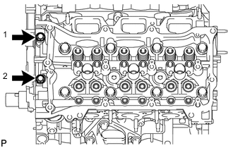
Tighten the 2 bolts in the order shown in the illustration.
- Torque:
- 30 N*m { 306 kgf*cm, 22 ft.*lbf }
Note
Thoroughly wipe clean any seal packing.
-
-
INSTALL REAR WATER BY-PASS JOINT
-
INSTALL VALVE STEM CAP
-
INSTALL VALVE LASH ADJUSTER ASSEMBLY
-
INSTALL NO. 1 VALVE ROCKER ARM SUB-ASSEMBLY
-
INSTALL CAMSHAFT BEARING CAP (for Bank 2)
-
INSTALL CAMSHAFT HOUSING SUB-ASSEMBLY LH
-
INSTALL CAMSHAFT BEARING CAP (for Bank 1)
-
INSTALL CAMSHAFT HOUSING SUB-ASSEMBLY RH
-
INSTALL NO. 3 CHAIN TENSIONER ASSEMBLY
-
INSTALL CAMSHAFT TIMING GEARS AND NO. 2 CHAIN (for Bank 2)
-
INSTALL NO. 2 CHAIN TENSIONER ASSEMBLY
-
INSTALL CAMSHAFT TIMING GEARS AND NO. 2 CHAIN (for Bank 1)
-
INSTALL NO. 1 CHAIN VIBRATION DAMPER
-
INSTALL NO. 2 CHAIN VIBRATION DAMPER
-
INSTALL CRANKSHAFT TIMING SPROCKET
-
INSTALL NO. 1 IDLE GEAR SHAFT
-
INSTALL CHAIN SUB-ASSEMBLY
-
INSTALL CHAIN TENSIONER SLIPPER
-
INSTALL NO. 1 CHAIN TENSIONER ASSEMBLY
-
INSPECT VALVE TIMING
-
INSTALL TIMING CHAIN COVER SUB-ASSEMBLY
-
Install the timing chain cover Click here.
-