MANIFOLD ABSOLUTE PRESSURE SENSOR ON-VEHICLE INSPECTION
PROCEDURE
-
INSPECT AIR PRESSURE SENSOR
-
Inspect the power source voltage.
-
Disconnect the air pressure sensor connector.
-
Turn the ignition switch to ON.
-
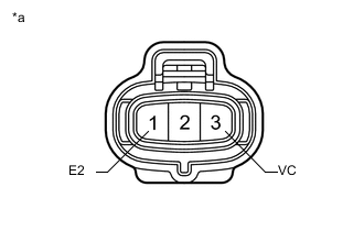
Text in Illustration *a Front view of wire harness connector
(to Air Pressure Sensor)
Measure the voltage according to the value(s) in the table below.
Standard Voltage Tester Connection Switch Condition Specified Condition 3 (VC) - 1 (E2) Ignition switch ON 4.75 to 5.25 V If the result is not as specified, inspect the wire harness and ECM.
-
Turn the ignition switch off.
-
Connect the air pressure sensor connector.
-
-
Check the pressure.
-
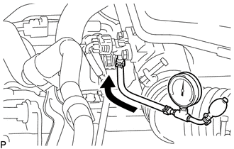
Connect a pressure gauge to the air pressure sensor as shown in the illustration.
-
Connect the GTS to the DLC3.
-
Turn the ignition switch to ON.
-
Turn the GTS on
-
Enter the following menus: Powertrain / Engine and ECT / Data List / Air Pump Pressure (absolute).
-
Check that the pressure displayed on the GTS fluctuates when applying pressure to the air pressure sensor with the pressure gauge.
OK Pressure fluctuates in response to pressure applied with pressure gauge. Tech Tips
The GTS displays the air pump pressure (Air Pump Pressure (absolute)) as absolute pressure.
If the result is not as specified, replace the air pressure sensor.
-
-