ENGINE ASSEMBLY REMOVAL

PROCEDURE
-
RECOVER REFRIGERANT FROM REFRIGERATION SYSTEM
-
DISCHARGE FUEL SYSTEM PRESSURE
-
DISCONNECT CABLE FROM NEGATIVE BATTERY TERMINAL
Note
-
After turning the engine switch off, waiting time may be required before disconnecting the cable from the battery terminal. Therefore, make sure to read the disconnecting the cable from the battery terminal notice before proceeding with work Click here.
-
When disconnecting the cable, some systems need to be initialized after the cable is reconnected Click here.
-
-
REMOVE HOOD SUB-ASSEMBLY
-
Disconnect the washer nozzle hose.
-
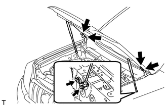
Remove the 8 bolts and hood.
Note
If the hood support is detached from the ball joint, it become non-reusable. Therefore, do not detach the hood support from the ball joint unless replacing it.
-
-
REMOVE COWL TOP VENTILATOR LOUVER SUB-ASSEMBLY
-
Remove the cowl top ventilator louver Click here.
-
-
REMOVE FRONT BUMPER COVER LOWER
-
Remove the clip, 5 bolts and front bumper cover lower.
-
-
REMOVE NO. 1 ENGINE UNDER COVER SUB-ASSEMBLY
-
Remove the 4 bolts.
-
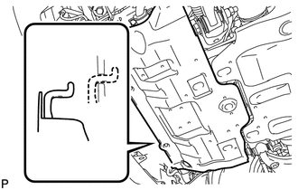
Unhook the engine under cover from the vehicle body as shown in the illustration.
-
-
REMOVE TRANSMISSION UNDER COVER
-
Remove the 2 bolts and transmission under cover.
-
-
REMOVE REAR ENGINE UNDER COVER ASSEMBLY
-
Remove the 4 bolts and rear engine under cover.
-
-
REMOVE FRONT FENDER APRON SEAL LH
-
Remove the 5 clips and front fender apron seal.
-
-
REMOVE FRONT FENDER APRON SEAL RH
-
Remove the 5 clips and front fender apron seal.
-
-
REMOVE FRONT NO. 1 FENDER APRON TO FRAME SEAL LH
-
Remove the 5 clips and front No. 1 fender apron to frame seal.
-
-
REMOVE FRONT NO. 1 FENDER APRON TO FRAME SEAL RH
-
Remove the 5 clips and front No. 1 fender apron to frame seal.
-
-
REMOVE UPPER RADIATOR SUPPORT SEAL
-
Remove the 13 clips and upper radiator support seal.
-
-
DRAIN ENGINE OIL
-
DRAIN ENGINE COOLANT
-
DISCONNECT CABLE FROM POSITIVE BATTERY TERMINAL
-
REMOVE BATTERY HOLD DOWN CLAMP
-
REMOVE BATTERY
-
REMOVE BATTERY TRAY
-
REMOVE V-BANK COVER
-
REMOVE FRONT BUMPER COVER
-
Remove the front bumper cover Click here.
-
-
REMOVE AIR CLEANER CAP AND HOSE
-
REMOVE AIR CLEANER CASE SUB-ASSEMBLY
-
REMOVE FRONT BUMPER CENTER UPPER RETAINER
-
REMOVE RADIATOR SIDE DEFLECTOR RH
-
REMOVE RADIATOR SIDE DEFLECTOR LH
-
REMOVE NO. 1 RADIATOR HOSE
-
REMOVE NO. 2 RADIATOR HOSE
-
REMOVE RADIATOR RESERVOIR
-
DISCONNECT OIL COOLER TUBE (w/ Warmer)
-
DISCONNECT OIL COOLER TUBE (w/ Air Cooled Transmission Oil Cooler)
-
REMOVE FAN SHROUD
-
REMOVE RADIATOR ASSEMBLY
-
REMOVE AIR TUBE ASSEMBLY (w/ Secondary Air Injection System)
-
REMOVE INTAKE AIR SURGE TANK
-
REMOVE FAN AND GENERATOR V BELT
-
DISCONNECT VANE PUMP ASSEMBLY
-
DISCONNECT DISCHARGE HOSE SUB-ASSEMBLY
-
DISCONNECT SUCTION HOSE SUB-ASSEMBLY
-
REMOVE COOLER COMPRESSOR ASSEMBLY
-
REMOVE FRONT EXHAUST PIPE ASSEMBLY
-
Remove the front exhaust pipe Click here.
-
-
REMOVE MANIFOLD STAY
-
REMOVE AIR TUBE (w/ Secondary Air Injection System)
-
DISCONNECT NO. 2 STEERING INTERMEDIATE SHAFT SUB-ASSEMBLY (for RHD)
-
for Manual tilt and manual telescopic steering column:
Disconnect the No. 2 steering intermediate shaft Click here.
-
for Power tilt and power telescopic steering column:
Disconnect the No. 2 steering intermediate shaft Click here.
-
-
REMOVE NO. 1 EXHAUST MANIFOLD HEAT INSULATOR
-
REMOVE EXHAUST MANIFOLD SUB-ASSEMBLY RH
-
REMOVE NO. 2 MANIFOLD STAY
-
REMOVE NO. 2 AIR TUBE (w/ Secondary Air Injection System)
-
REMOVE NO. 2 EXHAUST MANIFOLD HEAT INSULATOR
-
REMOVE EXHAUST MANIFOLD SUB-ASSEMBLY LH
-
REMOVE WIRING HARNESS CLAMP BRACKET
-
REMOVE GENERATOR ASSEMBLY
-
REMOVE STARTER ASSEMBLY
-
REMOVE DRIVE PLATE AND TORQUE CONVERTER CLUTCH SETTING BOLT (for Automatic Transmission)
-
DISCONNECT ENGINE WIRE
-
Remove the bolt and disconnect the connector.
-
Remove the glove compartment door Click here.
-
Disconnect the ECM connector.
-
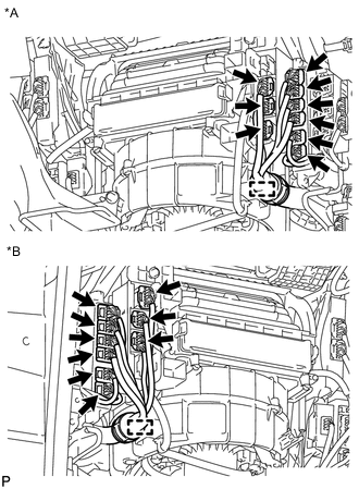
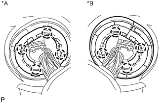
Text in Illustration *A for LHD *B for RHD Detach the clamp and disconnect the 9 connectors.
-
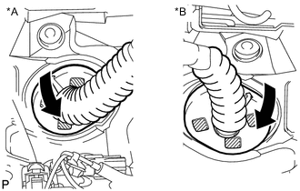
Text in Illustration *A for LHD *B for RHD Detach the grommet from the wire harness support.
-
Text in Illustration *A for LHD *B for RHD Detach the 4 claws to remove the wire harness support from the vehicle, and then pull out the ECM connector to remove it from the vehicle.
-
-
-
DISCONNECT HEATER WATER HOSE ASSEMBLY
-
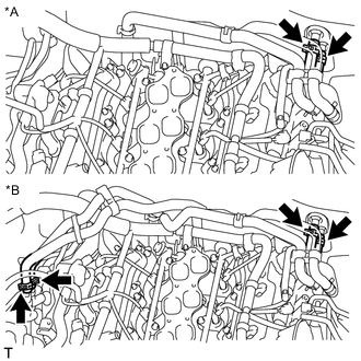
Text in Illustration *A w/o Rear Heater *B w/ Rear Heater w/o Rear heater:
Disconnect the 2 hoses and heater water hose.
-
w/ Rear heater:
Disconnect the 4 hoses and heater water hose.
-
-
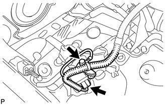
DISCONNECT NO. 1 AND NO. 2 FUEL PIPES
-
Remove the No. 2 fuel pipe clamp from the fuel tube connector.
-
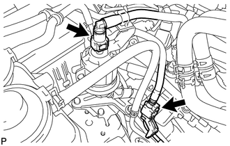
Disconnect the No. 1 and No. 2 fuel pipes Click here.
-
-
REMOVE FRONT PROPELLER SHAFT ASSEMBLY
-
REMOVE PROPELLER SHAFT ASSEMBLY
-
REMOVE MANUAL TRANSMISSION ASSEMBLY (for Manual Transmission)
-
Remove the manual transmission from the vehicle Click here.
-
-
REMOVE AUTOMATIC TRANSMISSION ASSEMBLY (for Automatic Transmission)
-
Remove the automatic transmission from the vehicle Click here.
-
-
REMOVE REAR NO. 1 ENGINE MOUNTING INSULATOR (for Automatic Transmission)
-
REMOVE REAR NO. 1 ENGINE MOUNTING INSULATOR (for Manual Transmission)
-
DISCONNECT SUCTION HOSE SUB-ASSEMBLY
-
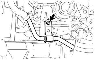
Remove the bolt and disconnect the suction hose.
-
-
DISCONNECT OIL COOLER TUBE SUB-ASSEMBLY (for Automatic Transmission)
-
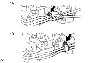
Text in Illustration *A w/o Air Cooled Transmission Oil Cooler *B w/ Air Cooled Transmission Oil Cooler Remove the bolt and disconnect the oil cooler tube.
-
-
REMOVE CLUTCH COVER ASSEMBLY (for Manual Transmission)
-
REMOVE CLUTCH DISC ASSEMBLY (for Manual Transmission)
-
REMOVE FLYWHEEL SUB-ASSEMBLY (for Manual Transmission)
-
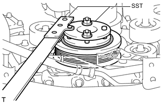
Using SST, hold the crankshaft.
- SST
- 09213-54015 ( 91651-60855 )
- 09330-00021
-
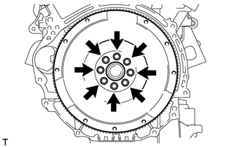
Remove the 8 bolts and flywheel.
Note
Do not reuse the bolts.
-
-
REMOVE DRIVE PLATE AND RING GEAR SUB-ASSEMBLY (for Automatic Transmission)
-

Using SST, hold the crankshaft.
- SST
- 09213-54015 ( 91651-60855 )
- 09330-00021
-
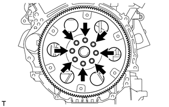
Remove the 8 bolts, rear spacer, drive plate and front spacer.
-
-
REMOVE ENGINE ASSEMBLY
-
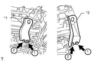
Text in Illustration *1 No. 1 Engine Hanger *2 No. 2 Engine Hanger Install 2 engine hangers with 4 bolts as shown in the illustration.
- Torque:
- 33 N*m { 337 kgf*cm, 24 ft.*lbf }
Tech Tips
No. 1 Engine Hanger 12281-31110 No. 2 Engine Hanger 12282-31140 Bolt 91671-C0830 -
Attach an engine sling device and hang the engine with a chain block.
-
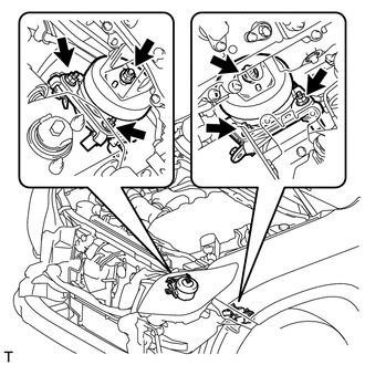
Remove the 6 nuts from the front engine mounting insulator LH and RH.
-
Lift the engine out of the vehicle carefully.
Note
Make sure the engine is clear of all wiring and hoses.
-
Remove the front engine mounting insulator LH and RH.
-
Place the engine onto a work bench.
-
-
INSTALL ENGINE STAND
-
Install the engine onto an engine stand with bolts.
-