ECD SYSTEM(w/ Urea SCR System), Diagnostic DTC:U010E
| DTC Code | DTC Name |
|---|---|
| U010E | Lost Communication with Reductant Control Module |
DESCRIPTION
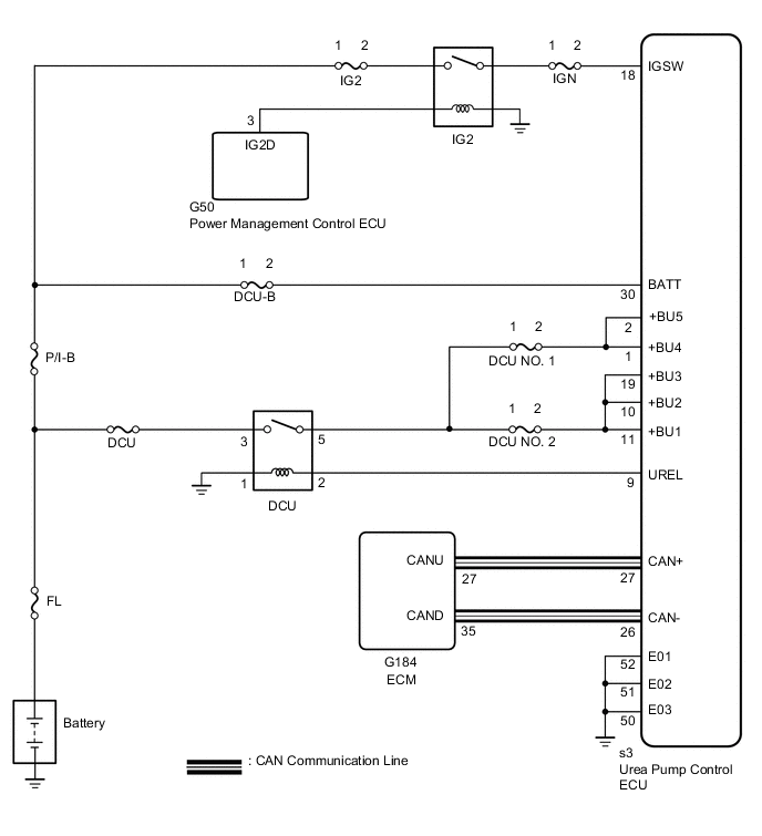
The ECM sends and receives data to and from the urea pump control ECU via local CAN communication.
| DTC Detection Drive Pattern | DTC Detection Condition | Trouble Area |
|---|---|---|
| 1.6 seconds or more after turning the engine switch on (IG). | Communication stops between the ECM and the urea pump control ECU for 1.6 seconds or more. (1 trip detectionlogic) |
|
MONITOR DESCRIPTION
The ECM stores a DTC when a communication malfunction occurs between the ECM and urea pump control ECU.
WIRING DIAGRAM
CAUTION / NOTICE / HINT
Note
Inspect the fuses of circuits related to this system before performing the following inspection procedure.
Tech Tips
Read freeze frame data using the GTS. Freeze frame data records the engine condition when malfunctions are detected. When troubleshooting, freeze frame data can help determine if the vehicle was moving or stationary, if the engine was warmed up or not, and other data from the time the malfunction occurred.
PROCEDURE
-
CHECK DTC OUTPUT
-
Connect the GTS to the DLC3.
-
Turn the engine switch on (IG) and turn the GTS on.
-
According to the display on the GTS, select "Health Check".
-
Check for currently output system DTCs.
Result Result Proceed to DTC U010E is output A DTC U010E and other DTCs are output* B Tech Tips
*: If any other DTCs are output, perform troubleshooting for those DTCs first.
B 
GO TO DTC CHART Click here
A 
-
-
CHECK HARNESS AND CONNECTOR (UREA PUMP CONTROL ECU - ECM)
-
Disconnect the urea pump control ECU connector.
-
Disconnect the ECM connector.
-
Measure the resistance according to the value(s) in the table below.
Standard Resistance Tester Connection Condition Specified Condition s3-27 (CAN+) - G184-27 (CANU) Always Below 1 Ω s3-26 (CAN-) - G184-35 (CAND) Always Below 1 Ω s3-27 (CAN+) or G184-27 (CANU) - Body ground and other terminals Always 10 kΩ or higher s3-26 (CAN-) or G184-35 (CAND) - Body ground and other terminals Always 10 kΩ or higher
NG
REPAIR OR REPLACE HARNESS AND CONNECTOR
OK
-
-
CHECK UREA PUMP CONTROL ECU (BATT TERMINAL)
-
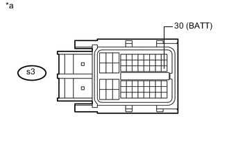
Text in Illustration *a Front view of wire harness connector
(to Urea Pump Control ECU)
Disconnect the urea pump control ECU connector.
-
Measure the voltage according to the value(s) in the table below.
Standard Voltage Tester Connection Switch Condition Specified Condition s3-30 (BATT) - Body ground Always 11 to 14 V
NG
REPLACE UREA PUMP CONTROL ECU Click here
OK
-
-
CHECK DCU MAIN RELAY (DCU)
-
Inspect the DCU main relay Click here.
NG
REPLACE DCU MAIN RELAY (DCU)
OK
-
-
CHECK UREA PUMP CONTROL ECU (UREL TERMINAL)
-
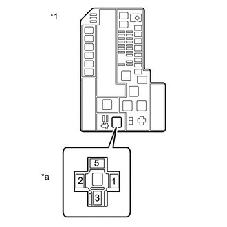
Text in Illustration *1 Front view of wire harness connector
(to DCU Relay)
*a Engine Room Relay Block Remove the DCU relay from the engine room relay block.
-
Turn the engine switch on (IG).
-
Measure the voltage according to the value(s) in the table below.
Standard Voltage Tester Connection Condition Specified Condition DCU relay terminal 2 - Body ground Engine switch on (IG) 11 to 14 V
NG 
CHECK HARNESS AND CONNECTOR (ENGINE ROOM RELAY BLOCK - UREA PUMP CONTROL ECU) Click here
OK
-
-
CHECK HARNESS AND CONNECTOR (ENGINE ROOM RELAY BLOCK - UREA PUMP CONTROL ECU)
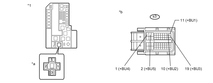
Text in Illustration *1 Engine Room Relay Block - - *a Front view of wire harness connector
(to DCU Relay)
*b Front view of wire harness connector
(to Urea Pump Control ECU)
-
Remove the DCU relay from the engine room relay block.
-
Disconnect the urea pump control ECU connector.
-
Measure the resistance according to the value(s) in the table below.
Standard Resistance Tester Connection Condition Specified Condition DCU relay terminal 5 - s3-11 (+BU1) Always Below 1 Ω DCU relay terminal 5 - s3-10 (+BU2) Always Below 1 Ω DCU relay terminal 5 - s3-19 (+BU3) Always Below 1 Ω DCU relay terminal 5 - s3-1 (+BU4) Always Below 1 Ω DCU relay terminal 5 - s3-2 (+BU5) Always Below 1 Ω DCU relay terminal 1 - Body ground Always Below 1 Ω DCU relay terminal 5 or s3-11 (+BU1) - Body ground and other terminals Always 10 kΩ or higher DCU relay terminal 5 or s3-10 (+BU2) - Body ground and other terminals Always 10 kΩ or higher DCU relay terminal 5 or s3-19 (+BU3) - Body ground and other terminals Always 10 kΩ or higher DCU relay terminal 5 or s3-1 (+BU4) - Body ground and other terminals Always 10 kΩ or higher DCU relay terminal 5 or s3-2 (+BU5) - Body ground and other terminals Always 10 kΩ or higher
OK
REPAIR OR REPLACE HARNESS AND CONNECTOR (NO.1 ENGINE ROOM RELAY BLOCK - BATTERY)
NG
REPAIR OR REPLACE HARNESS AND CONNECTOR
-
-
CHECK HARNESS AND CONNECTOR (ENGINE ROOM RELAY BLOCK - UREA PUMP CONTROL ECU)
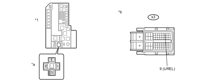
Text in Illustration *1 Engine Room Relay Block - - *a Front view of wire harness connector
(to DCU Relay)
*b Front view of wire harness connector
(to Urea Pump Control ECU)
-
Remove the DCU relay from the engine room relay block.
-
Disconnect the urea pump control ECU connector.
-
Measure the resistance according to the value(s) in the table below.
Standard Resistance Tester Connection Condition Specified Condition DCU relay terminal 2- s3-9 (UREL) Always Below 1 Ω DCU relay terminal 2or s3-9 (UREL) - Body ground and other terminals Always 10 kΩ or higher
OK
REPLACE UREA PUMP CONTROL ECU Click here
NG
REPAIR OR REPLACE HARNESS AND CONNECTOR
-