ECD SYSTEM(w/ Urea SCR System), Diagnostic DTC:P2564, P2565
| DTC Code | DTC Name |
|---|---|
| P2564 | Turbocharger/Supercharger Boost Control Position Sensor "A" Circuit Low |
| P2565 | Turbocharger/Supercharger Boost Control Position Sensor "A" Circuit High |
DESCRIPTION
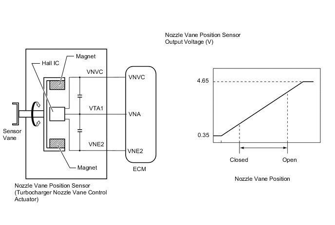
The variable nozzle vane type turbocharger consists primarily of a compressor wheel, turbine wheel, nozzle vane, unison ring, DC motor and nozzle vane position sensor.
The nozzle vane position sensor consists of a Hall IC and a magnetic yoke that rotates in unison with the movement of the linkage that actuates the nozzle vane. The nozzle vane position sensor converts the changes in the magnetic flux that are caused by the rotation of the DC motor (hence, the rotation of the magnetic yoke) into electric signals, and outputs them to the ECM. The ECM determines the actual nozzle vane position from the electric signals in order to calculate the target nozzle vane position.
| DTC Detection Drive Pattern | DTC Detection Condition | Trouble Area |
|---|---|---|
| Engine switch on (IG) for 2 seconds or more | VNA voltage is 0.1 V or less for 2.1 seconds (1 trip detection logic). |
|
| DTC Detection Drive Pattern | DTC Detection Condition | Trouble Area |
|---|---|---|
| Engine switch on (IG) for 2 seconds or more | VNA voltage is 4.9 V or higher for 2.1 seconds (1 trip detection logic). |
|
Tech Tips
If DTC P2564 and/or P2565 is stored due to the nozzle vane being stuck open, the following symptoms may appear:
-
- Lack of power
-
- Vehicle surge or hesitation under light or medium load
WIRING DIAGRAM
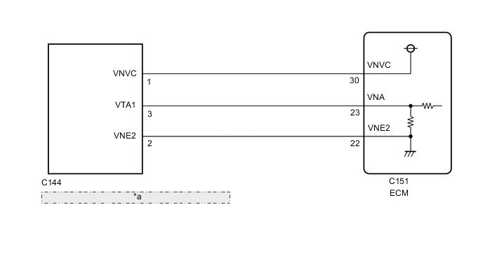
| *a | Nozzle Vane Position Sensor (Turbocharger Nozzle Vane Control Actuator) |
CAUTION / NOTICE / HINT
Note
After replacing the ECM, the new ECM needs registration (See page ) and initialization Click here.
Tech Tips
Read freeze frame data using the GTS. Freeze frame data records the engine condition when malfunctions are detected. When troubleshooting, freeze frame data can help determine if the vehicle was moving or stationary, if the engine was warmed up or not, and other data from the time the malfunction occurred.
PROCEDURE
-
CHECK TERMINAL VOLTAGE (POWER SOURCE OF NOZZLE VANE POSITION SENSOR)
-
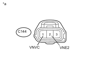
Text in Illustration *a Front view of wire harness connector
(to Nozzle Vane Position Sensor)
Disconnect the nozzle vane position sensor connector.
-
Turn the engine switch on (IG).
-
Measure the voltage according to the value(s) in the table below.
Standard Voltage Tester Connection Switch Condition Specified Condition C144-1 (VNVC) - C144-2 (VNE2) Engine switch on (IG) 4.5 to 5.5 V -
Reconnect the nozzle vane position sensor connector.
NG 
CHECK ECM (POWER SOURCE OF NOZZLE VANE POSITION SENSOR) Click here
OK 
-
-
INSPECT NOZZLE VANE POSITION SENSOR (VNA VOLTAGE)
-
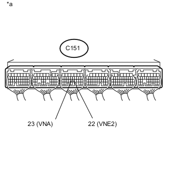
Text in Illustration *a Component with harness connected
(ECM)
Measure the voltage according to the value(s) in the table below.
Standard Voltage Tester Connection Switch Condition Specified Condition C151-23 (VNA) - C151-22 (VNE2) Engine switch on (IG) 2.3 to 2.7 V
OK
CONFIRM WHETHER MALFUNCTION HAS BEEN SUCCESSFULLY REPAIRED Click here
NG
-
-
CHECK HARNESS AND CONNECTOR (NOZZLE VANE POSITION SENSOR - ECM)
-
Disconnect the nozzle vane position sensor connector.
-
Disconnect the ECM connector.
-
Measure the resistance according to the value(s) in the table below.
Standard Resistance Tester Connection Condition Specified Condition C144-3 (VTA1) - C151-23 (VNA) Always Below 1 Ω C144-2 (VNE2) - C151-22 (VNE2) Always Below 1 Ω C144-3 (VTA1) or C151-23 (VNA) - Body ground and other terminals Always 10 kΩ or higher C144-2 (VNE2) or C151-22 (VNE2) - Body ground and other terminals Always 10 kΩ or higher -
Reconnect the nozzle vane position sensor connector.
-
Reconnect the ECM connector.
NG
REPAIR OR REPLACE HARNESS OR CONNECTOR Click here
OK
-
-
CHECK ECM (CHECK RESISTANCE)
-
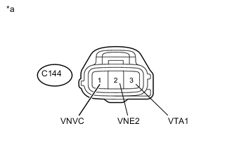
Text in Illustration *a Front view of wire harness connector
(to Nozzle Vane Position Sensor)
Disconnect the nozzle vane position sensor connector.
-
Measure the resistance according to the value(s) in the table below.
Standard Resistance Tester Connection Condition Specified Condition C144-1 (VNVC) - C144-3 (VTA1) Engine switch off No short or open circuit C144-3 (VTA1) - C144-2 (VNE2) -
Reconnect the nozzle vane position sensor connector.
NG
REPLACE ECM Click here
OK
-
-
REPLACE TURBOCHARGER NOZZLE VANE CONTROL ACTUATOR (NOZZLE VANE POSITION SENSOR)
-
Replace the turbocharger nozzle vane control actuator Click here.
NEXT
CONFIRM WHETHER MALFUNCTION HAS BEEN SUCCESSFULLY REPAIRED Click here
-
-
CHECK ECM (POWER SOURCE OF NOZZLE VANE POSITION SENSOR)
-
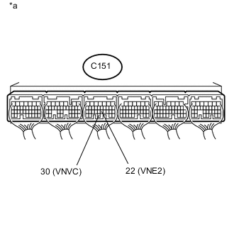
Text in Illustration *a Component with harness connected
(ECM)
Measure the voltage according to the value(s) in the table below.
Standard Voltage Tester Connection Switch Condition Specified Condition C151-30 (VNVC) - C151-22 (VNE2) Engine switch on (IG) 4.5 to 5.5 V
OK
REPAIR OR REPLACE HARNESS OR CONNECTOR Click here
NG
-
-
REPLACE ECM
-
Replace the ECM Click here.
NEXT
CONFIRM WHETHER MALFUNCTION HAS BEEN SUCCESSFULLY REPAIRED Click here
-
-
REPAIR OR REPLACE HARNESS OR CONNECTOR
-
Repair or replace the harness or connector.
NEXT
-
-
CONFIRM WHETHER MALFUNCTION HAS BEEN SUCCESSFULLY REPAIRED
-
Connect the GTS to the DLC3.
-
Clear the DTCs Click here.
-
Turn the engine switch off and leave the vehicle for 15 seconds.
-
Turn the engine switch on (IG) for 2 seconds or more.
-
Confirm that the DTC is not output again.
Tech Tips
Perform the following procedure using the GTS to determine whether or not the DTC judgment has been carried out.
-
Enter the following menus: Powertrain / Engine and ECT / Utility / All Readiness.
-
Input DTC P2564 and/or P2565.
-
Check that STATUS is NORMAL. If STATUS is INCOMPLETE or N/A, idle the engine.
-
NEXT 
END
-