ECD SYSTEM(w/ Urea SCR System), Diagnostic DTC:P2470, P2471
| DTC Code | DTC Name |
|---|---|
| P2470 | Exhaust Gas Temperature Sensor Circuit Low (Bank 1 Sensor 4) |
| P2471 | Exhaust Gas Temperature Sensor Circuit High (Bank 1 Sensor 4) |
DESCRIPTION
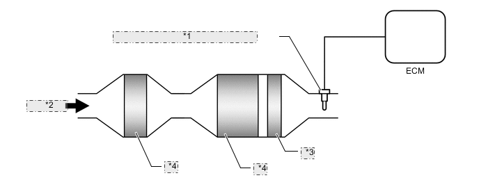
| *1 | No. 4 Exhaust Gas Temperature Sensor |
| *2 | Exhaust Gas |
| *3 | ASC Catalyst |
| *4 | SCR Catalyst |
The No. 4 exhaust gas temperature sensor is installed after the SCR catalyst to detect the exhaust gas temperature. A thermistor built into the No. 4 exhaust gas temperature sensor changes its resistance value according to the exhaust gas temperature. The lower the exhaust gas temperature, the higher the thermistor resistance value. The higher the exhaust gas temperature, the lower the thermistor resistance value. The No. 4 exhaust gas temperature sensor is connected to the ECM. The 5 V power source voltage is applied to the No. 4 exhaust gas temperature sensor from terminal THSO via resistor R. Resistor R and the No. 4 exhaust gas temperature sensor are connected in series. When the resistance value of the No. 4 exhaust gas temperature sensor changes in accordance with the exhaust gas temperature, the voltage at terminal THSO also changes. The No. 4 exhaust gas temperature sensor monitors the temperature downstream of the SCR catalyst.
| DTC Detection Drive Pattern | DTC Detection Condition | Trouble Area |
|---|---|---|
| Idle the engine for 3 seconds after warming up the engine (the engine coolant temperature is 70°C (158°F) or higher) and allowing 1 minute to elapse after starting the engine. | No. 4 Exhaust gas temperature sensor output voltage is below 0.11 V for 3 seconds or more when all conditions are met. (1 trip detection logic):
|
|
| DTC Detection Drive Pattern | DTC Detection Condition | Trouble Area |
|---|---|---|
| Idle the engine for 3 seconds after warming up the engine (the engine coolant temperature is 70°C (158°F) or higher) and allowing 1 minute to elapse after starting the engine. | No. 4 Exhaust gas temperature sensor output voltage is higher than 4.89 V for 3 seconds or more when all conditions are met. (1 trip detection logic):
|
|
| DTC No. | Data List |
|---|---|
| P2470 P2471 |
SCR Temperature |
MONITOR DESCRIPTION
The ECM constantly monitors the output voltages from the No. 4 exhaust gas temperature sensors in order to detect problems with the sensors. When the sensor output voltage deviates from the normal operating range (between 0.11 V and 4.89 V) for more than 3 seconds after the engine is warmed up, the ECM interprets this as malfunction of the sensor circuit and illuminates the MIL.
WIRING DIAGRAM
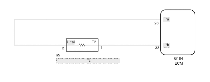
| *a | THSO |
| *b | ETSO |
| *c | No. 4 Exhaust Gas Temperature Sensor |
CAUTION / NOTICE / HINT
Tech Tips
Read freeze frame data using the GTS. Freeze frame data records the engine condition when malfunctions are detected. When troubleshooting, freeze frame data can help determine if the vehicle was moving or stationary, if the engine was warmed up or not, and other data from the time the malfunction occurred.
PROCEDURE
-
INSPECT NO. 4 EXHAUST GAS TEMPERATURE SENSOR
-
Inspect the No. 4 exhaust gas temperature sensor Click here.
NG 
REPLACE NO. 4 EXHAUST GAS TEMPERATURE SENSOR Click here
OK 
-
-
CHECK HARNESS AND CONNECTOR (NO. 4 EXHAUST GAS TEMPERATURE SENSOR - ECM)
-
Disconnect the No. 4 exhaust gas temperature sensor.
-
Disconnect the ECM connector.
-
Measure the resistance according to the value(s) in the table below.
Standard Resistance Tester Connection Condition Specified Condition s5-2 (THSO) - G184-26 (THSO) Always Below 1 Ω s5-1 (E2) - G184-33 (ETSO) Always Below 1 Ω s5-2 (THSO) or G184-26 (THSO) - Body ground and other terminals Always 10 kΩ or higher s5-1 (E2) or G184-33 (ETSO) - Body ground and other terminals Always 10 kΩ or higher -
Reconnect the No. 4 exhaust gas temperature sensor.
-
Reconnect the ECM connector.
NG
REPAIR OR REPLACE HARNESS OR CONNECTOR Click here
OK
-
-
REPLACE ECM
-
Replace the ECM Click here.
NEXT
CONFIRM WHETHER MALFUNCTION HAS BEEN SUCCESSFULLY REPAIRED Click here
-
-
REPLACE NO. 4 EXHAUST GAS TEMPERATURE SENSOR
-
Replace the No. 4 exhaust gas temperature sensor Click here.
NEXT
CONFIRM WHETHER MALFUNCTION HAS BEEN SUCCESSFULLY REPAIRED Click here
-
-
REPAIR OR REPLACE HARNESS OR CONNECTOR
-
Repair or replace the harness or connector.
NEXT
-
-
CONFIRM WHETHER MALFUNCTION HAS BEEN SUCCESSFULLY REPAIRED
-
Connect the GTS to the DLC3.
-
Clear the DTCs Click here.
-
Start the engine.
-
Idle the engine for 3 seconds or more after warming up the engine (the engine coolant temperature is 70°C (158°F) or higher) and allowing 1 minute to elapse after starting the engine.
-
Enter the following menus: Powertrain / Engine and ECT / Trouble Codes.
-
Confirm that the DTC is not output again.
NEXT 
END
-