ECD SYSTEM(w/ Urea SCR System), Diagnostic DTC:P2454, P2455
| DTC Code | DTC Name |
|---|---|
| P2454 | Diesel Particulate Filter Pressure Sensor "A" Circuit Low |
| P2455 | Diesel Particulate Filter Pressure Sensor "A" Circuit High |
DESCRIPTION
Tech Tips
-
For more information on the differential pressure sensor and Diesel Particulate Filter (DPF), refer to the following procedures Click here.
-
If P2454 and/or P2455 is present, refer to the DTC chart for DPF system Click here.
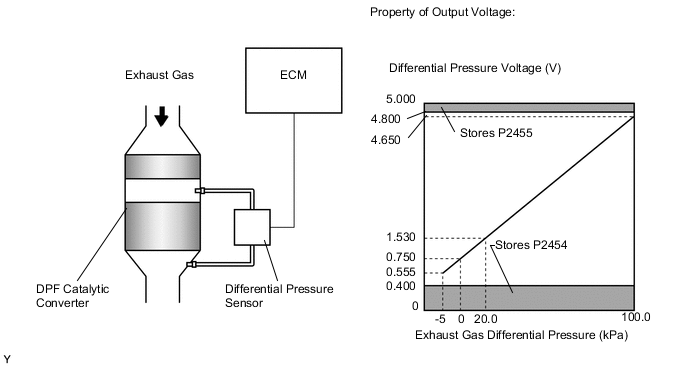
The two sensing chambers of the differential pressure sensor are mounted to monitor the pressure before and after the DPF catalytic converter. The sensor itself is not located on the engine assembly in order to reduce the influence of vibration.
The ECM compares the exhaust gas pressure before and after the DPF catalytic converter by monitoring the pressure using the upstream and downstream sensing chambers of the differential pressure sensor. If the difference in pressure exceeds a predetermined level, the ECM judges that the catalytic converter is clogged with particulate matter (PM). When the ECM judges that a partially clogged condition exists, the ECM begins to perform PM forced regeneration.
When the output voltage of the sensor deviates from the normal operating range, the ECM interprets this as a malfunction of the sensor circuit, and sets DTC P2454 or P2455, and illuminates the MIL.
| DTC Detection Drive Pattern | DTC Detection Condition | Trouble Area |
|---|---|---|
| Engine switch on (IG) for 5 seconds | Differential pressure sensor output voltage is below 0.4 V for 3 seconds or more. (1 trip detection logic) |
|
| DTC Detection Drive Pattern | DTC Detection Condition | Trouble Area |
|---|---|---|
| Engine switch on (IG) for 5 seconds | Differential pressure sensor output voltage is higher than 4.8 V for 3 seconds or more. (1 trip detection logic) |
|
| DTC No. | Data List |
|---|---|
| P2454 P2455 |
DPF Differential Pressure |
Tech Tips
-
DTC P2453 (Diesel Particulate Filter Pressure Sensor "A" Circuit Range / Performance) will be stored if there is incorrect vacuum hose routing to the differential pressure sensor assembly.
-
After confirming DTC P2454 and P2455, check the differential pressure in the "Powertrain / Engine and ECT / Data List / DPF Differential Pressure" menu using the GTS.
| Condition | DPF Differential Pressure Output | Sensor Condition |
|---|---|---|
| Engine switch on (IG) | Approximately 0 kPa | Normal |
| Always | -5 kPa or less or higher than 99 kPa | Open or short circuit |
| 4000 rpm (No engine load) | Negative output | Incorrect hose routing |
MONITOR DESCRIPTION
In order to detect abnormality in the differential pressure sensor, the ECM always monitors the output voltage from the sensor. When the sensor output voltage deviates from the normal operating range (between 0.4 V and 4.8 V) for more than 3 seconds, the ECM interprets this as a malfunction in the sensor circuit and illuminates the MIL.
WIRING DIAGRAM
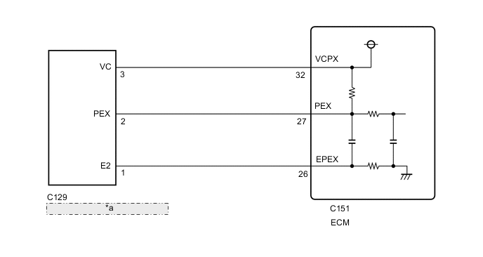
| *a | Differential Pressure Sensor |
CAUTION / NOTICE / HINT
Note
After replacing the ECM, the new ECM needs registration (See page ) and initialization Click here.
Tech Tips
Read freeze frame data using the GTS. Freeze frame data records the engine condition when malfunctions are detected. When troubleshooting, freeze frame data can help determine if the vehicle was moving or stationary, if the engine was warmed up or not, and other data from the time the malfunction occurred.
PROCEDURE
-
CHECK TERMINAL VOLTAGE (POWER SOURCE OF DIFFERENTIAL PRESSURE SENSOR)
-
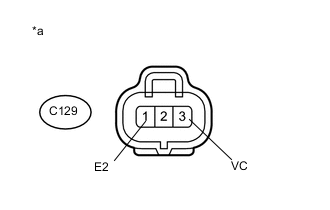
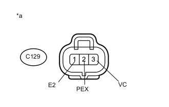
Text in Illustration *a Front view of wire harness connector
(to Differential Pressure Sensor)
Disconnect the differential pressure sensor connector.
-
Turn the engine switch on (IG).
-
Measure the voltage according to the value(s) in the table below.
Standard Voltage Tester Connection Switch Condition Specified Condition C129-3 (VC) - C129-1 (E2) Engine switch on (IG) 4.5 to 5.5 V -
Reconnect the differential pressure sensor connector.
NG 
CHECK ECM (POWER SOURCE OF DIFFERENTIAL PRESSURE SENSOR) Click here
OK 
-
-
INSPECT DIFFERENTIAL PRESSURE SENSOR (PEX VOLTAGE)
-
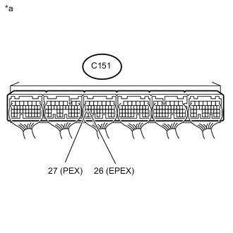
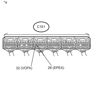
Text in Illustration *a Component with harness connected
(ECM)
Measure the resistance according to the value(s) in the table below.
Standard Resistance Tester Connection Condition Specified Condition C151-27 (PEX) - C151-26 (EPEX) Engine switch on (IG) 0.4 to 4.8 V
OK
REPLACE ECM Click here
NG
-
-
CHECK WIRE HARNESS (DIFFERENTIAL PRESSURE SENSOR - ECM)
-
Disconnect the differential pressure sensor connector.
-
Disconnect the ECM connector.
-
Measure the resistance according to the value(s) in the table below.
Standard Resistance Tester Connection Condition Specified Condition C129-2 (PEX) - C151-27 (PEX) Always Below 1 Ω C129-3 (VC) - C151-32 (VCPX) Always Below 1 Ω C129-1 (E2) - C151-26 (EPEX) Always Below 1 Ω C129-2 (PEX) or C151-27 (PEX) - Body ground and other terminals Always 10 kΩ or higher C129-3 (VC) or C151-32 (VCPX) - Body ground and other terminals Always 10 kΩ or higher -
Reconnect the differential pressure sensor connector.
-
Reconnect the ECM connector.
NG
REPAIR OR REPLACE HARNESS OR CONNECTOR Click here
OK
-
-
CHECK ECM (CHECK RESISTANCE)
-
Text in Illustration *a Front view of wire harness connector
(to Differential Pressure Sensor)
Disconnect the differential pressure sensor connector.
-
Measure the voltage according to the value(s) in the table below.
Standard Voltage Tester Connection Switch Condition Specified Condition C129-3 (VC) - C129-2 (PEX) Engine switch off No short or open circuit C129-2 (PEX) - C129-1 (E2) -
Reconnect the differential pressure sensor connector.
NG
REPLACE ECM Click here
OK
-
-
REPLACE DIFFERENTIAL PRESSURE SENSOR
-
Replace the differential pressure sensor Click here.
NEXT
CONFIRM WHETHER MALFUNCTION HAS BEEN SUCCESSFULLY REPAIRED Click here
-
-
CHECK ECM (POWER SOURCE OF DIFFERENTIAL PRESSURE SENSOR)
-
Text in Illustration *a Component with harness connected
(ECM)
Measure the voltage according to the value(s) in the table below.
Standard Voltage Tester Connection Condition Specified Condition C151-32 (VCPX) - C151-26 (EPEX) Engine switch on (IG) 4.5 to 5.5 V
OK
REPAIR OR REPLACE HARNESS OR CONNECTOR Click here
NG
-
-
REPLACE ECM
-
Replace the ECM Click here.
NEXT
CONFIRM WHETHER MALFUNCTION HAS BEEN SUCCESSFULLY REPAIRED Click here
-
-
REPAIR OR REPLACE HARNESS OR CONNECTOR
-
Repair or replace the harness or connector.
NEXT
-
-
CONFIRM WHETHER MALFUNCTION HAS BEEN SUCCESSFULLY REPAIRED
-
Connect the GTS to the DLC3.
-
Clear the DTCs Click here.
-
Turn the engine switch on (IG) and wait for 5 seconds.
-
Enter the following menus: Powertrain / Engine and ECT / Trouble Codes.
-
Confirm that the DTC is not output again.
NEXT 
END
-