ECD SYSTEM(w/ Urea SCR System), Diagnostic DTC:P2120, P2122, P2123, P2125, P2127, P2128, P2138
| DTC Code | DTC Name |
|---|---|
| P2120 | Throttle / Pedal Position Sensor / Switch "D" Circuit |
| P2122 | Throttle / Pedal Position Sensor / Switch "D" Circuit Low Input |
| P2123 | Throttle / Pedal Position Sensor / Switch "D" Circuit High Input |
| P2125 | Throttle / Pedal Position Sensor / Switch "E" Circuit |
| P2127 | Throttle / Pedal Position Sensor / Switch "E" Circuit Low Input |
| P2128 | Throttle / Pedal Position Sensor / Switch "E" Circuit High Input |
| P2138 | Throttle / Pedal Position Sensor / Switch "D" / "E" Voltage Correlation |
DESCRIPTION
Tech Tips
-
This is the repair procedure for the accelerator pedal position sensor.
-
This electrical throttle system does not use a throttle cable.
-
This accelerator pedal position sensor is a non-contact type.
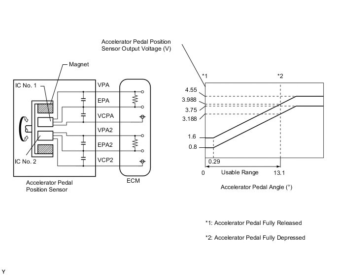
The accelerator pedal position sensor is mounted on the accelerator pedal sensor assembly and detects the opening angle of the accelerator pedal. Since this sensor is electronically controlled with Hall-effect elements, accurate control and reliability can be obtained. It has 2 sensors to detect the accelerator position and a malfunction of the accelerator pedal position sensor.
In the accelerator pedal position sensor, the voltage applied to terminals VPA and VPA2 of the ECM changes between 0.5 V and 4.8 V in proportion to the opening angle of the accelerator pedal. The VPA is a signal to indicate the actual accelerator pedal opening angle which is used for engine control, and the VPA2 is a signal to indicate information about the opening angle which is used for detecting malfunctions. The ECM judges the current opening angle of the accelerator pedal using signals from terminals VPA and VPA2, and the ECM controls the injection volume based on these signals.
| DTC Detection Drive Pattern | DTC Detection Condition | Trouble Area |
|---|---|---|
| Engine switch on (IG)
|
Condition (a) continues for 0.5 seconds (1 trip detection logic): (a) VPA is below 0.4 V and VPA2 is more than 2.7 deg, or VPA is higher than 4.8 V. |
|
| DTC Detection Drive Pattern | DTC Detection Condition | Trouble Area |
|---|---|---|
| Engine switch on (IG)
|
Conditions (a) and (b) continue for 0.5 seconds (1 trip detection logic): (a) VPA is below 0.4 V. (b) VPA2 is more than 2.7 deg. |
|
| DTC Detection Drive Pattern | DTC Detection Condition | Trouble Area |
|---|---|---|
| Engine switch on (IG)
|
Condition (a) continues for 2.0 seconds (1 trip detection logic): (a) VPA is higher than 4.8 V. |
|
| DTC Detection Drive Pattern | DTC Detection Condition | Trouble Area |
|---|---|---|
| Engine switch on (IG)
|
Condition (a) continues for 0.5 seconds (1 trip detection logic): (a) VPA2 is below 1.2 V and VPA is more than 2.7 deg, or VPA2 is higher than 4.8 V and VPA is higher than 0.4 V but below 3.45 V. |
|
| DTC Detection Drive Pattern | DTC Detection Condition | Trouble Area |
|---|---|---|
| Engine switch on (IG)
|
Conditions (a) and (b) continue for 0.5 seconds (1 trip detection logic): (a) VPA2 is below 1.2 V. (b) VPA1 is more than 2.7 deg. |
|
| DTC Detection Drive Pattern | DTC Detection Condition | Trouble Area |
|---|---|---|
| Engine switch on (IG)
|
Conditions (a) and (b) continue for 2.0 seconds (1 trip detection logic): (a) VPA2 is higher than 4.8 V. (b) VPA is higher than 0.4 V but below 3.45 V. |
|
| DTC Detection Drive Pattern | DTC Detection Condition | Trouble Area |
|---|---|---|
| Engine switch on (IG)
|
Conditions (a) or (b) continue for 2.0 seconds (1 trip detection logic): (a) The difference between VPA and VPA2 is less than 0.02 V. (b) VPA is below 0.4 V and VPA2 is below 1.2 V. |
|
| DTC No. | Data List |
|---|---|
| P2120 P2122 P2123 P2125 P2127 P2128 P2138 |
|
WIRING DIAGRAM
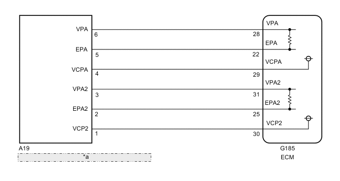
| *a | Accelerator Pedal Position Sensor (Accelerator Pedal Sensor Assembly) |
CAUTION / NOTICE / HINT
Note
After replacing the ECM, the new ECM needs registration (See page ) and initialization Click here.
Tech Tips
Read freeze frame data using the GTS. Freeze frame data records the engine condition when malfunctions are detected. When troubleshooting, freeze frame data can help determine if the vehicle was moving or stationary, if the engine was warmed up or not, and other data from the time the malfunction occurred.
PROCEDURE
-
READ VALUE USING GTS (ACCELERATOR PEDAL POSITION)
-
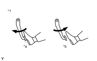
Text in Illustration *1 Accelerator Pedal Assembly *a Depressed *b Released Connect the GTS to the DLC3.
-
Turn the engine switch on (IG) and turn the GTS on.
-
Enter the following menus: Powertrain / Engine and ECT / Data List / Accel Sens. No.1 Volt % and Accel Sens. No.2 Volt %.
-
Read the values.
Standard Voltage Accelerator Pedal Accel Sens. No.1 Volt % Accel Sens. No.2 Volt % Released 10 to 22% 24 to 40% Depressed 52 to 90% 68 to 99% Result Result Proceed to NG A OK B
B 
CONFIRM WHETHER MALFUNCTION HAS BEEN SUCCESSFULLY REPAIRED Click here
A 
-
-
CHECK ECM (ACCELERATOR PEDAL POSITION SENSOR VOLTAGE)
-
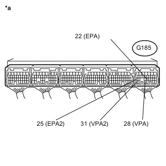
Text in Illustration *a Component with harness connected
(ECM)
Measure the voltage according to the value(s) in the table below.
Standard Voltage Tester Connection Switch Condition Specified Condition G185-29 (VCPA) - G185-22 (EPA) Engine switch on (IG) 4.5 to 5.5 V G185-30 (VCP2) - G185-25 (EPA2) Engine switch on (IG) 4.5 to 5.5 V
NG
REPLACE ECM Click here
OK
-
-
INSPECT ACCELERATOR PEDAL SENSOR ASSEMBLY (VPA, VPA2 VOLTAGE)
-
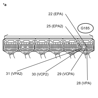
Text in Illustration *a Component with harness connected
(ECM)
Measure the voltage according to the value(s) in the table below.
Standard Voltage Tester Connection Switch Condition Specified Condition G185-28 (VPA) - G185-22 (EPA) Engine switch on (IG), accelerator pedal fully released 0.5 to 1.1 V Engine switch on (IG), accelerator pedal fully depressed 0.5 to 1.1 V C185-31 (VPA2) - G185-25 (EPA2) Engine switch on (IG), accelerator pedal fully released 0.9 to 2.3 V Engine switch on (IG), accelerator pedal fully depressed 0.9 to 2.3 V
OK
REPLACE ECM Click here
NG
-
-
INSPECT ECM TERMINAL VOLTAGE (VCPA AND VCP2 TERMINALS)
-
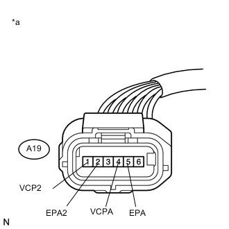
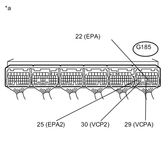
Text in Illustration *a Front view of wire harness connector
(to Accelerator Pedal Position Sensor)
Disconnect the accelerator pedal sensor assembly connector.
-
Measure the voltage according to the value(s) in the table below.
Standard Voltage Tester Connection Switch Condition Specified Condition A19-4 (VCPA) - A19-5 (EPA) Engine switch on (IG) 4.5 to 5.5 V A19-1 (VCP2) - A19-2 (EPA2) Engine switch on (IG) 4.5 to 5.5 V -
Reconnect the accelerator pedal sensor assembly connector.
NG
REPAIR OR REPLACE HARNESS OR CONNECTOR Click here
OK
-
-
CHECK HARNESS AND CONNECTOR (ACCELERATOR PEDAL POSITION SENSOR - ECM)
-
Disconnect the accelerator pedal sensor assembly connector.
-
Disconnect the ECM connector.
-
Measure the resistance according to the value(s) in the table below.
Standard Resistance Tester Connection Condition Specified Condition A19-6 (VPA) - G50-28 (VPA) Always Below 1 Ω A19-5 (EPA) - G185-22 (EPA) Always Below 1 Ω A19-3 (VPA2) - G185-31 (VPA2) Always Below 1 Ω A19-2 (EPA2) - G185-25 (EPA2) Always Below 1 Ω A19-6 (VPA) or G185-28 (VPA) - Body ground and other terminals Always 10 kΩ or higher A19-5 (EPA) or G185-22 (EPA) - Body ground and other terminals Always 10 kΩ or higher A19-3 (VPA2) or G185-31 (VPA2) - Body ground and other terminals Always 10 kΩ or higher A19-2 (EPA2) or G185-25 (EPA2) - Body ground and other terminals Always 10 kΩ or higher -
Reconnect the accelerator pedal sensor assembly connector.
-
Reconnect the ECM connector.
NG
CONFIRM WHETHER MALFUNCTION HAS BEEN SUCCESSFULLY REPAIRED Click here
OK
-
-
CHECK ECM (CHECK RESISTANCE)
-
Disconnect the accelerator pedal sensor assembly connector.
-
Measure the resistance according to the value(s) in the table below.
Standard Resistance Tester Connection Condition Specified Condition G185-29 (VCPA) - G185-28 (VPA) Engine switch off No short or open circuit G185-28 (VPA) - G185-22 (EPA) Engine switch off No short or open circuit G185-30 (VCP2) - G185-31 (VPA2) Engine switch off No short or open circuit G185-31 (VPA2) - G185-25 (EPA2) Engine switch off No short or open circuit -
Reconnect the accelerator pedal sensor assembly connector.
NG
REPLACE ECM Click here
OK
-
-
REPLACE ACCELERATOR PEDAL SENSOR ASSEMBLY
-
Replace the accelerator pedal sensor assembly Click here.
NEXT
CONFIRM WHETHER MALFUNCTION HAS BEEN SUCCESSFULLY REPAIRED Click here
-
-
REPLACE ECM
-
Replace the ECM Click here.
NEXT
CONFIRM WHETHER MALFUNCTION HAS BEEN SUCCESSFULLY REPAIRED Click here
-
-
REPAIR OR REPLACE HARNESS OR CONNECTOR
-
Repair or replace the harness or connector.
NEXT
-
-
CONFIRM WHETHER MALFUNCTION HAS BEEN SUCCESSFULLY REPAIRED
-
Connect the GTS to the DLC3.
-
Clear the DTCs Click here.
-
Turn the engine switch off and leave the vehicle for 30 seconds.
-
Turn the engine switch on (IG).
-
Fully release the accelerator pedal for 3 seconds or more, then depress it partway for 3 seconds or more, and then fully depress it for 3 seconds or more.
-
Enter the following menus: Powertrain / Engine and ECT / Trouble Codes.
-
Confirm that the DTC is not output again.
NEXT 
END
-