ECD SYSTEM(w/ Urea SCR System), Diagnostic DTC:P064C, P066B, P066D, P066F, P0671, P0672, P0673, P0674, P067B, P166F
| DTC Code | DTC Name |
|---|---|
| P064C | Glow Plug Control Module |
| P066B | Cylinder 1 Glow Plug Control Circuit High |
| P066D | Cylinder 2 Glow Plug Control Circuit High |
| P066F | Cylinder 3 Glow Plug Control Circuit High |
| P0671 | Cylinder 1 Glow Plug Circuit/Open |
| P0672 | Cylinder 2 Glow Plug Circuit/Open |
| P0673 | Cylinder 3 Glow Plug Circuit/Open |
| P0674 | Cylinder 4 Glow Plug Circuit/Open |
| P067B | Cylinder 4 Glow Plug Control Circuit High |
| P166F | Glow Plug Control Module Circuit Short |
DESCRIPTION
| DTC Detection Drive Pattern | DTC Detection Condition | Trouble Area |
|---|---|---|
| Enter check mode | The MOS inside the glow plug control unit is detected as being stuck on 3 times while the glow plugs are on (2 trip detection logic). | Glow plug controller |
| DTC Detection Drive Pattern | DTC Detection Condition | Trouble Area |
|---|---|---|
| Enter check mode | A short circuit in the No. 1 glow plug circuit is detected 3 times while the glow plugs are on (2 trip detection logic). |
|
| DTC Detection Drive Pattern | DTC Detection Condition | Trouble Area |
|---|---|---|
| Enter check mode | A short circuit in the No. 2 glow plug circuit is detected 3 times while the glow plugs are on (2 trip detection logic). |
|
| DTC Detection Drive Pattern | DTC Detection Condition | Trouble Area |
|---|---|---|
| Enter check mode | A short circuit in the No. 3 glow plug circuit is detected 3 times while the glow plugs are on (2 trip detection logic). |
|
| DTC Detection Drive Pattern | DTC Detection Condition | Trouble Area |
|---|---|---|
| Enter check mode | A short circuit in the No. 4 glow plug circuit is detected 3 times while the glow plugs are on (2 trip detection logic). |
|
| DTC Detection Drive Pattern | DTC Detection Condition | Trouble Area |
|---|---|---|
| Enter check mode | An open circuit in the No. 1 glow plug circuit is detected 3 times while the glow plugs are on (2 trip detection logic). |
|
| DTC Detection Drive Pattern | DTC Detection Condition | Trouble Area |
|---|---|---|
| Enter check mode | An open circuit in the No. 2 glow plug circuit is detected 3 times while the glow plugs are on (2 trip detection logic). |
|
| DTC Detection Drive Pattern | DTC Detection Condition | Trouble Area |
|---|---|---|
| Enter check mode | An open circuit in the No. 3 glow plug circuit is detected 3 times while the glow plugs are on (2 trip detection logic). |
|
| DTC Detection Drive Pattern | DTC Detection Condition | Trouble Area |
|---|---|---|
| Enter check mode | An open circuit in the No. 4 glow plug circuit is detected 3 times while the glow plugs are on (2 trip detection logic). |
|
| DTC Detection Drive Pattern | DTC Detection Condition | Trouble Area |
|---|---|---|
| Enter check mode | A short circuit in a wire harness between the glow plugs is detected 3 times while the glow plugs are on (2 trip detection logic). |
|
WIRING DIAGRAM
Refer to DTC P052F Click here
CAUTION / NOTICE / HINT
Note
-
Inspect the fuses of circuits related to this system before performing the following inspection procedure.
-
After replacing the ECM, the new ECM needs registration (See page ) and initialization Click here.
PROCEDURE
-
CHECK DTC OUTPUT
-
Connect the GTS to the DLC3.
-
Turn the engine switch on (IG) and turn the GTS on.
-
Enter the following menus: Powertrain / Engine and ECT / Trouble Codes.
-
Read the DTCs.
Result Result Proceed to DTC P0671, P0672, P0673 and/or P0674 is output A DTC P066B, P066D, P066F and/or P067B is output B DTC P064C and/or P166F is output C
B 
CHECK HARNESS AND CONNECTOR Click here
C
CHECK HARNESS AND CONNECTOR Click here
A 
-
-
CHECK GLOW PLUG CONTROLLER
-
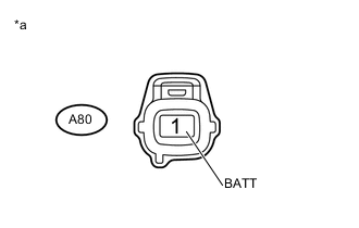
Text in Illustration *a Front view of wire harness connector
(to Glow Plug Controller)
Disconnect the glow plug controller connector.
-
Measure the voltage according to the value(s) in the table below.
Standard Voltage Tester Connection Condition Specified Condition A80-1 (BATT) - Body ground Always 11 to 14 V -
Reconnect the glow plug controller connector.
NG
INSPECT GLOW RELAY Click here
OK
-
-
CHECK HARNESS AND CONNECTOR
-
Disconnect connectors of the glow plug controller.
-
Remove the No. 1 glow plug connector from the glow plug.
-
Measure the resistance according to the value(s) in the table below.
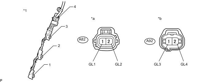
Standard Resistance Tester Connection Condition Specified Condition A82-1 (GL1) - No. 1 glow plug connector terminal 1 Always Below 1 Ω A82-2 (GL2) - No. 1 glow plug connector terminal 2 Always Below 1 Ω A92-1 (GL3) - No. 1 glow plug connector terminal 3 Always Below 1 Ω A92-2 (GL4) - No. 1 glow plug connector terminal 4 Always Below 1 Ω Text in Illustration *1 No. 1 Glow Plug Connector - - *a Front view of wire harness connector
(to Glow Plug Controller)
*b Front view of wire harness connector
(to Glow Plug Controller)
-
Reconnect the glow plug controller connector.
-
Reinstall the No. 1 glow plug connector.
NG
REPAIR OR REPLACE HARNESS OR CONNECTOR Click here
OK
-
-
INSPECT GLOW PLUG ASSEMBLY
-
Clear the DTCs Click here.
-
Exchange the glow plugs of the malfunctioning cylinders (the cylinders indicated by output DTCs) with the glow plugs of normally functioning cylinders.
-
Turn the engine switch on (IG) and turn the GTS on.
-
Using the GTS, switch the ECM from normal mode to check mode Click here.
-
Enter the following menus: Powertrain / Engine and ECT / Trouble Codes.
-
Read the DTCs.
Result Result Proceed to Same DTCs (that have been erased) A Other DTCs B Tech Tips
Check for DTCs in check mode.
A
REPLACE GLOW PLUG CONTROLLER Click here
B
-
-
REPLACE GLOW PLUG ASSEMBLY
-
Replace the glow plug assembly Click here.
NEXT
CONFIRM WHETHER MALFUNCTION HAS BEEN SUCCESSFULLY REPAIRED Click here
-
-
REPAIR OR REPLACE HARNESS OR CONNECTOR
-
Repair or replace the harness or connector.
NEXT
-
-
CONFIRM WHETHER MALFUNCTION HAS BEEN SUCCESSFULLY REPAIRED
-
Connect the GTS to the DLC3.
-
Clear the DTCs Click here.
-
Turn the engine switch off for 30 seconds or more.
-
Turn the engine switch on (IG) and turn the GTS on.
-
Using the GTS, switch the ECM from normal mode to check mode Click here.
-
Enter the following menus: Powertrain / Engine and ECT / Trouble Codes.
-
Confirm that the DTC is not output again.
Tech Tips
Check for DTCs in check mode.
NEXT 
END
-
-
CHECK HARNESS AND CONNECTOR
-
Disconnect connectors of the glow plug controller.
-
Remove the No. 1 glow plug connector from the glow plug.
-
Measure the resistance according to the value(s) in the table below.
Standard Resistance Tester Connection Condition Specified Condition A82-1 (GL1) or No. 1 glow plug connector terminal 1 - Body ground Always Below 1 Ω A82-2 (GL2) or No. 1 glow plug connector terminal 2 - Body ground Always Below 1 Ω A92-1 (GL3) or No. 1 glow plug connector terminal 3 - Body ground Always Below 1 Ω A92-2 (GL4) or No. 1 glow plug connector terminal 4 - Body ground Always Below 1 Ω Text in Illustration *1 No. 1 Glow Plug Connector - - *a Front view of wire harness connector
(to Glow Plug Controller)
*b Front view of wire harness connector
(to Glow Plug Controller)
Tech Tips
Make sure that there are no short circuits to the battery.
-
Reconnect the glow plug controller connector.
-
Reinstall the No. 1 glow plug connector.
NG
REPAIR OR REPLACE HARNESS OR CONNECTOR Click here
OK
-
-
REPLACE GLOW PLUG CONTROLLER
-
Replace the glow plug controller Click here.
NEXT
CONFIRM WHETHER MALFUNCTION HAS BEEN SUCCESSFULLY REPAIRED Click here
-
-
REPAIR OR REPLACE HARNESS OR CONNECTOR
-
Repair or replace the harness or connector.
NEXT
-
-
CONFIRM WHETHER MALFUNCTION HAS BEEN SUCCESSFULLY REPAIRED
-
Connect the GTS to the DLC3.
-
Clear the DTCs Click here.
-
Turn the engine switch off for 30 seconds or more.
-
Turn the engine switch on (IG) and turn the GTS on.
-
Using the GTS, switch the ECM from normal mode to check mode Click here.
-
Enter the following menus: Powertrain / Engine and ECT / Trouble Codes.
-
Read the DTCs.
OK No DTC is output. Tech Tips
Check for DTCs in check mode.
OK
END
NG
-
-
REPLACE GLOW PLUG ASSEMBLY
-
Replace the glow plug assembly Click here.
NEXT
CONFIRM WHETHER MALFUNCTION HAS BEEN SUCCESSFULLY REPAIRED Click here
-
-
CHECK HARNESS AND CONNECTOR
-
Disconnect connectors of the glow plug controller.
-
Remove the No. 1 glow plug connector from the glow plug.
-
Measure the resistance according to the value(s) in the table below.
Standard Resistance Tester Connection Condition Specified Condition A82-1 (GL1) or No. 1 glow plug connector terminal 1 - Body ground Always Below 1 Ω A82-2 (GL2) or No. 1 glow plug connector terminal 2 - Body ground Always Below 1 Ω A92-1 (GL3) or No. 1 glow plug connector terminal 3 - Body ground Always Below 1 Ω A92-2 (GL4) or No. 1 glow plug connector terminal 4 - Body ground Always Below 1 Ω Text in Illustration *1 No. 1 Glow Plug Connector - - *a Front view of wire harness connector
(to Glow Plug Controller)
*b Front view of wire harness connector
(to Glow Plug Controller)
Tech Tips
Make sure that there are no short circuits to the battery.
-
Reconnect the glow plug controller connector.
-
Reinstall the No. 1 glow plug connector.
NG
REPAIR OR REPLACE HARNESS OR CONNECTOR Click here
OK
-
-
REPLACE GLOW PLUG CONTROLLER
-
Replace the glow plug controller Click here.
NEXT
CONFIRM WHETHER MALFUNCTION HAS BEEN SUCCESSFULLY REPAIRED Click here
-
-
REPAIR OR REPLACE HARNESS OR CONNECTOR
-
Repair or replace the harness or connector.
NEXT
-
-
CONFIRM WHETHER MALFUNCTION HAS BEEN SUCCESSFULLY REPAIRED
-
Connect the GTS to the DLC3.
-
Clear the DTCs Click here.
-
Turn the engine switch off for 30 seconds or more.
-
Turn the engine switch on (IG) and turn the GTS on.
-
Using the GTS, switch the ECM from normal mode to check mode Click here.
-
Enter the following menus: Powertrain / Engine and ECT / Trouble Codes.
-
Confirm that the DTC is not output again.
Tech Tips
Check for DTCs in check mode.
NEXT
END
-
-
INSPECT GLOW RELAY
-
Inspect the GLOW relay Click here.
NG
REPLACE GLOW RELAY
OK
-
-
CHECK HARNESS AND CONNECTOR
-
Disconnect the cable from the negative (-) battery terminal.
-
Disconnect the cable from the positive (+) battery terminal.
-
Remove the GLOW relay assembly.
-
Remove the No. 1 glow plug connector from the glow plug.
-
Disconnect connectors of the glow plug controller.
-
Disconnect the ECM connectors.
-
Measure the resistance according to the value(s) in the table below.
Standard Resistance Tester Connection Condition Specified Condition GLOW relay terminal 5 - Battery positive terminal Always Below 1 Ω GLOW relay terminal 1 - Body ground Always Below 1 Ω GLOW relay terminal 3 - A80-1 (BATT) Always Below 1 Ω GLOW relay terminal 2 - G184-15 (GREL) Always Below 1 Ω GLOW relay terminal 5 or Battery positive terminal - Body ground and other terminals Always 10 kΩ or higher GLOW relay terminal 3 or A80-1 (BATT) - Body ground and other terminals Always 10 kΩ or higher GLOW relay terminal 2 or G184-15 (GREL) - Body ground and other terminals Always 10 kΩ or higher
OK
REPLACE ECM Click here
NG
REPAIR OR REPLACE HARNESS OR CONNECTOR Click here
-