ECD SYSTEM(w/ Urea SCR System), Diagnostic DTC:P0107, P0108
| DTC Code | DTC Name |
|---|---|
| P0107 | Manifold Absolute Pressure / Barometric Pressure Circuit Low Input |
| P0108 | Manifold Absolute Pressure / Barometric Pressure Circuit High Input |
DESCRIPTION
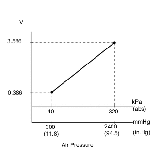
The manifold absolute pressure sensor detects the intake manifold pressure. The ECM determines the basic injection volume and injection advance timing based on the voltage output by the manifold absolute pressure sensor.
The manifold absolute pressure sensor monitors the absolute pressure inside the intake manifold (default is 0 kPa [0 mmHg, 0 in.Hg]). As a result, the ECM controls the air-fuel ratio so that it reaches the proper level under any driving conditions.
| DTC Detection Drive Pattern | DTC Detection Condition | Trouble Area |
|---|---|---|
| 2 seconds after engine is started, race engine for 1 second | After the engine is started, condition (a) continues for more than 0.5 seconds (1 trip detection logic): (a) Manifold absolute pressure sensor voltage is 0.1 V or less. |
|
| DTC Detection Drive Pattern | DTC Detection Condition | Trouble Area |
|---|---|---|
| 2 seconds after engine is started, race engine for 1 second | After the engine is started, condition (a) continues for more than 0.5 seconds (1 trip detection logic): (a) Manifold absolute pressure sensor voltage is 4.8 V or higher. |
|
| DTC No. | Data List |
|---|---|
| P0107 P0108 |
|
Tech Tips
-
If DTC P0107 and/or P0108 is stored, the following symptoms may appear:
-
Misfire
-
Combustion noise
-
Black smoke
-
White smoke
-
Lack of power
-
When DTC P0107 or P0108 is stored, check the intake manifold pressure by entering the following menus: Powertrain / Engine and ECT / Data List / MAP.
Reference GTS Displayed Malfunction 22 kPa (165 mmHg, 6.5 in.Hg)
-
Open in VC circuit
-
Open in PIMcircuit
-
Short in PIM circuit
320 kPa (2400 mmHg, 94.5 in.Hg) or higher
-
Open in E circuit
-
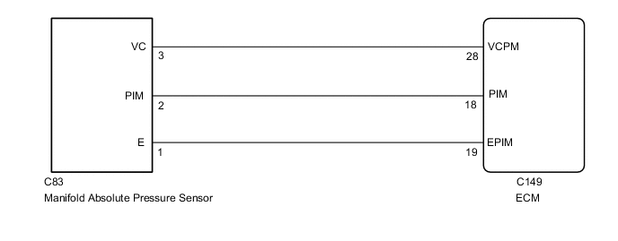
WIRING DIAGRAM
CAUTION / NOTICE / HINT
Note
After replacing the ECM, the new ECM needs registration (See page ) and initialization Click here.
Tech Tips
Read freeze frame data using the GTS. Freeze frame data records the engine condition when malfunctions are detected. When troubleshooting, freeze frame data can help determine if the vehicle was moving or stationary, if the engine was warmed up or not, and other data from the time the malfunction occurred.
PROCEDURE
-
READ VALUE USING GTS (MAP)
-
Connect the GTS to the DLC3.
-
Turn the engine switch on (IG) and turn the GTS on.
-
Enter the following menus: Powertrain / Engine and ECT / Data List / MAP.
-
Read the value.
OK Same as the actual atmospheric pressure. Tech Tips
-
Standard atmospheric pressure is 101 kPa. For every 100 m increase in elevation, pressure drops by 1 kPa. This varies by weather (high atmospheric pressure, low atmospheric pressure).
-
Also, check "Atmosphere Pressure" in the Data List.
-
OK 
CONFIRM WHETHER MALFUNCTION HAS BEEN SUCCESSFULLY REPAIRED Click here
NG 
-
-
CHECK ECM TERMINAL VOLTAGE (VC TERMINAL)
-
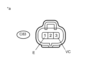
Text in Illustration *a Front view of wire harness connector
(to Manifold Absolute Pressure Sensor)
Disconnect the manifold absolute pressure sensor connector.
-
Measure the voltage according to the value(s) in the table below.
Standard Voltage Tester Connection Switch Condition Specified Condition C83-3 (VC) - C83-1 (E) Engine switch on (IG) 4.5 to 5.5 V -
Reconnect the manifold absolute pressure sensor connector.
NG
CHECK ECM (POWER SOURCE OF MANIFOLD ABSOLUTE PRESSURE SENSOR) Click here
OK
-
-
INSPECT MANIFOLD ABSOLUTE PRESSURE SENSOR (PIM VOLTAGE)
-
Measure the voltage according to the value(s) in the table below.
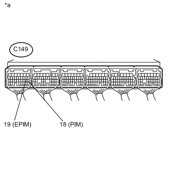
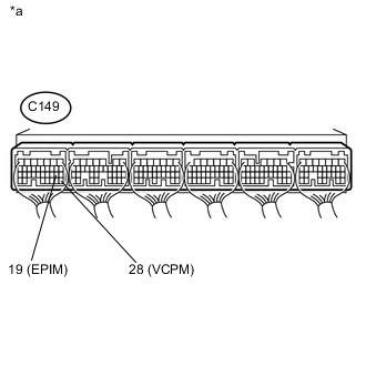
Standard Voltage Tester Connection Switch Condition Specified Condition C149-18 (PIM) - C149-19 (EPIM) Engine switch on (IG) 0.8 to 1.5 V Text in Illustration *a Component with harness connected
(ECM)
OK
REPLACE ECM Click here
NG
-
-
CHECK HARNESS AND CONNECTOR (MANIFOLD ABSOLUTE PRESSURE SENSOR - ECM)
-
Disconnect the manifold absolute pressure sensor connector.
-
Disconnect the ECM connector.
-
Measure the resistance according to the value(s) in the table below.
Standard Resistance Tester Connection Condition Specified Condition C83-2 (PIM) - C149-18 (PIM) Always Below 1 Ω C83-1 (E) - C149-19 (EPIM) Always Below 1 Ω C83-2 (PIM) or C149-18 (PIM) - Body ground and other terminals Always 10 kΩ or higher C83-1 (E) or C149-19 (EPIM) - Body ground and other terminals Always 10 kΩ or higher -
Reconnect the manifold absolute pressure sensor connector.
-
Reconnect the ECM connector.
NG
REPAIR OR REPLACE HARNESS OR CONNECTOR Click here
OK
-
-
CHECK ECM (CHECK RESISTANCE)
-
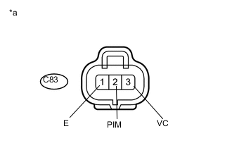
Text in Illustration *a Front view of wire harness connector
(to Manifold Absolute Pressure Sensor)
Disconnect the manifold absolute pressure sensor connector.
-
Measure the resistance according to the value(s) in the table below.
Standard Resistance Tester Connection Condition Specified Condition C83-3 (VC) - C83-2 (PIM) Engine switch off No short or open C83-2 (PIM) - C83-1 (E) -
Reconnect the manifold absolute pressure sensor connector.
NG
REPLACE ECM Click here
OK
-
-
REPLACE MANIFOLD ABSOLUTE PRESSURE SENSOR
-
Replace the manifold absolute pressure sensor Click here.
NEXT
CONFIRM WHETHER MALFUNCTION HAS BEEN SUCCESSFULLY REPAIRED Click here
-
-
CHECK ECM (POWER SOURCE OF MANIFOLD ABSOLUTE PRESSURE SENSOR)
-
Measure the voltage according to the value(s) in the table below.
Standard Voltage Tester Connection Switch Condition Specified Condition C149-28 (VCPM) - C149-19 (EPIM) Engine switch on (IG) 4.5 to 5.5 V Text in Illustration *a Component with harness connected
(ECM)
NG
REPLACE ECM Click here
OK
-
-
REPAIR OR REPLACE HARNESS OR CONNECTOR
-
Repair or replace the harness or connector.
NEXT
CONFIRM WHETHER MALFUNCTION HAS BEEN SUCCESSFULLY REPAIRED Click here
-
-
REPLACE ECM
-
Replace the ECM Click here.
NEXT
-
-
CONFIRM WHETHER MALFUNCTION HAS BEEN SUCCESSFULLY REPAIRED
-
Connect the GTS to the DLC3.
-
Clear the DTCs Click here.
-
Turn the engine switch off for 30 seconds or more.
-
Turn the GTS off.
-
Turn the engine switch on (IG) for 3 seconds and turn the GTS on.
-
After the engine is started for 2 seconds, race the engine for 1 second.
-
Confirm that the DTC is not output again.
Tech Tips
Perform the following procedure using the GTS to determine whether or not the DTC judgment has been carried out.
-
Enter the following menus: Powertrain / Engine and ECT / Utility / All Readiness.
-
Input DTC P0107 or P0108.
-
Check that STATUS is NORMAL. If STATUS is INCOMPLETE or N/A, race the engine for 1 minute, and then idle the engine for 5 minutes.
-
NEXT 
END
-