ECD SYSTEM(w/ Urea SCR System), Diagnostic DTC:P0087, P0190, P0192, P0193
| DTC Code | DTC Name |
|---|---|
| P0087 | Fuel Rail / System Pressure - Too Low |
| P0190 | Fuel Rail Pressure Sensor Circuit |
| P0192 | Fuel Rail Pressure Sensor Circuit Low Input |
| P0193 | Fuel Rail Pressure Sensor Circuit High Input |
DESCRIPTION
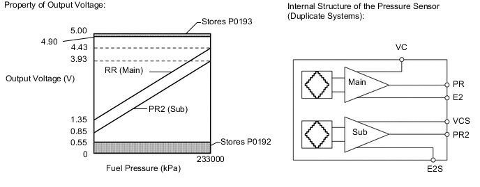
The ECM monitors the internal fuel pressure of the common rail using the fuel pressure sensor, and controls the pre-stroke control valve to regulate the internal pressure so that it reaches the target pressure. The pressure sensor is a semiconductor that varies electrical resistance when pressure is applied to its silicon chip. This sensor outputs a voltage in proportion to the internal fuel pressure.
| DTC Detection Drive Pattern | DTC Detection Condition | Trouble Area |
|---|---|---|
| After idling for 60 seconds, quickly increase engine speed to 2500 rpm repeatedly for 30 seconds | Fuel pressure sensor output voltage stays at fixed value a certain number of times (0.1 seconds or more). (1 trip detection logic) |
|
| DTC Detection Drive Pattern | DTC Detection Condition | Trouble Area |
|---|---|---|
| Engine switch on (IG) for 1 second | Fuel pressure sensor output voltage is 0.55 V or less, or 4.9 V or higher for 0.5 seconds. (1 trip detection logic) |
Tech Tips Trouble areas are related to the electrical system only (pumps are not involved) |
| DTC Detection Drive Pattern | DTC Detection Condition | Trouble Area |
|---|---|---|
| Engine switch on (IG) for 1 second | Fuel pressure sensor output voltage is 0.55 V or less for 0.5 seconds. (1 trip detection logic) |
Tech Tips Trouble areas are related to the electrical system only (pumps are not involved) |
| DTC Detection Drive Pattern | DTC Detection Condition | Trouble Area |
|---|---|---|
| Engine switch on (IG) for 1 second | Fuel pressure sensor output voltage is 4.9 V or higher for 0.5 seconds. (1 trip detection logic) |
Tech Tips Trouble areas are related to the electrical system only (pumps are not involved) |
| DTC No. | Data List |
|---|---|
| P0087 P0190 P0192 P0193 |
|
Tech Tips
-
Check Common Rail Pressure and compare it to Target Common Rail Pressure in the Data List by entering the following menus: Powertrain / Engine and ECT / Data List / Common Rail Pressure, Target Common Rail Pressure. Under stable conditions, the difference between Common Rail Pressure and Target Common Rail Pressure is 5000 kPa or less.
-
For more information on the fuel pressure sensor and common rail system, refer to System Description Click here.
-
If DTC P0087 is stored, the following symptoms may appear:
-
Black smoke
-
Poor drivability
-
Lack of power
-
Lack of power due to accelerator restriction performed by fail-safe function
-
If DTC P0190, P0192 and/or P0193 is stored, the following symptom may appear:
-
Lack of power due to accelerator restriction performed by fail-safe function
-
If DTC P0190, P0192 and/or P0193 is stored, "Common Rail Pressure" always displays 0 kPa or 240000 kPa.
MONITOR DESCRIPTION
- P0087 (Fuel pressure sensor output stays at fixed value):
-
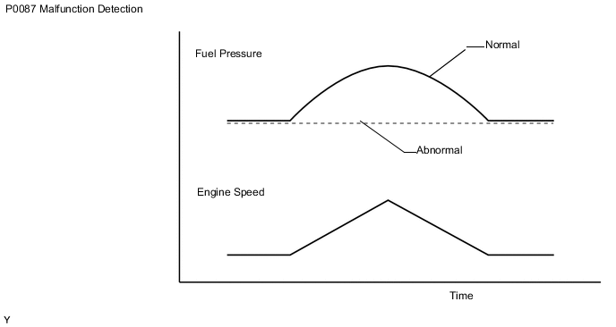
Under normal conditions, the internal fuel pressure of the common rail assembly usually fluctuates by 1000 to 2000 kPa (10 to 20 kgf/cm2, 145 to 290 psi) even when driving conditions are constant. This DTC is stored if there is no fluctuation of the fuel pressure. The internal fuel pressure is approximately 30000 to 50000 kPa (306 to 510 kgf/cm2, 4350 to 7250 psi) when idling, and it increases to approximately 80000 to 110000 kPa (816 to 1122 kgf/cm2, 11600 to 15950 psi) when running the engine at 3000 rpm.
If this DTC is stored, the ECM enters fail-safe mode and limits engine power. The ECM continues operating in fail-safe mode until the engine switch off.
-
The diagram below indicates that fuel pressure rises as engine speed increases, but for the malfunction indicated by this DTC, that does not happen.
-
Even if the system is normal, DTCs may be stored due to a drop in the fuel pressure after running out of fuel, etc. If DTCs P0087 and P1603 are both stored, clear these DTCs and perform a DTC check again.
-
- P0190, P0192 and P0193 (Open or short in fuel pressure sensor circuit):
These DTCs are stored if the fuel pressure sensor output voltage is out of the standard range due to an open or short malfunction of the sensor circuit.
If these DTCs are stored, the ECM enters fail-safe mode and limits the engine power. The ECM continues operating in fail-safe mode until the engine switch off.
WIRING DIAGRAM
| *a | Fuel Pressure Sensor |
CAUTION / NOTICE / HINT
Note
After replacing the ECM, the new ECM needs registration (See page ) and initialization Click here.
Tech Tips
Read freeze frame data using the GTS. Freeze frame data records the engine condition when malfunctions are detected. When troubleshooting, freeze frame data can help determine if the vehicle was moving or stationary, if the engine was warmed up or not, and other data from the time the malfunction occurred.
PROCEDURE
-
CHECK DTC OUTPUT
-
Connect the GTS to the DLC3.
-
Turn the engine switch on (IG) and turn the GTS on.
-
Enter the following menus: Powertrain / Engine and ECT / Trouble Codes.
-
Read the DTCs.
Result Result Proceed to DTC P0190, P0192 or P0193 is output A DTC P0087 is output* B Tech Tips
*: If DTCs P0087 and P1603 are stored, these DTCs may have been stored due to a drop in the fuel pressure after running out of fuel, etc. Therefore, clear these DTCs and perform a DTC check to confirm whether they are output again.
B 
REPLACE COMMON RAIL ASSEMBLY (FUEL PRESSURE SENSOR) Click here
A 
-
-
CHECK ECM (FUEL PRESSURE SENSOR VOLTAGE)
-
Text in Illustration *a Component with harness connected
(ECM)
Measure the voltage according to the value(s) in the table below.
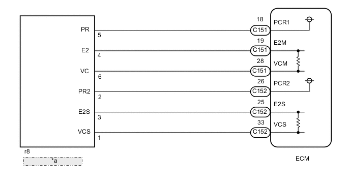
Standard Voltage Tester Connection Switch Condition Specified Condition C151-28 (VCM) - C151-19 (E2M) Engine switch on (IG) 4.5 to 5.5 V C152-33 (VCS) - C152-25 (E2S) Engine switch on (IG) 4.5 to 5.5 V
NG
REPLACE ECM Click here
OK
-
-
INSPECT FUEL PRESSURE SENSOR (PCR1, PCR2 VOLTAGE)
-
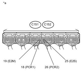
Text in Illustration *a Component with harness connected
(ECM)
Measure the voltage according to the value(s) in the table below.
Standard Voltage Tester Connection Switch Condition Specified Condition C151-18 (PCR1) - C151-19 (E2M) Idling 1.8 to 2.1 V C152-26 (PCR2) - C152-25 (E2S) Idling 1.2 to 1.5 V
NG
CHECK ECM (FUEL PRESSURE SENSOR VOLTAGE) Click here
OK
-
-
CHECK WHETHER DTC OUTPUT RECURS
-
Turn the engine switch on (IG).
-
Connect the GTS to the DLC3.
-
Clear the DTCs Click here.
-
Turn the engine switch off for 30 seconds or more.
-
Turn the engine switch on (IG) for 1 second or more.
-
Enter the following menus: Powertrain / Engine and ECT / Trouble Codes.
-
Read the DTCs.
Result Result Proceed to DTC P0190, P0192 or P0193 is output A DTC is not output B
A
REPLACE ECM Click here
B 
CHECK FOR INTERMITTENT PROBLEMS Click here
-
-
CHECK ECM (FUEL PRESSURE SENSOR VOLTAGE)
-
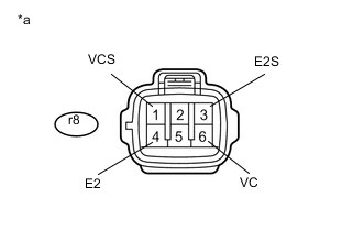
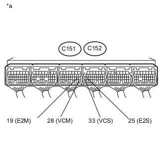
Text in Illustration *a Front view of wire harness connector
(to Fuel Pressure Sensor)
Disconnect the fuel pressure sensor connector.
-
Measure the voltage according to the value(s) in the table below.
Standard Voltage Tester Connection Switch Condition Specified Condition r8-6 (VC) - r8-4 (E2) Engine switch on (IG) 4.5 to 5.5 V r8-1 (VCS) - r8-3 (E2S) Engine switch on (IG) 4.5 to 5.5 V -
Reconnect the fuel pressure sensor connector.
NG
REPAIR OR REPLACE HARNESS OR CONNECTOR Click here
OK
-
-
CHECK HARNESS AND CONNECTOR (FUEL PRESSURE SENSOR - ECM)
-
Disconnect the fuel pressure sensor connector.
-
Disconnect the ECM connector.
-
Measure the resistance according to the value(s) in the table below.
Standard Resistance Tester Connection Condition Specified Condition r8-5 (PR) - C151-18 (PCR1) Always Below 1 Ω r8-4 (E2) - C151-19 (E2M) Always Below 1 Ω r8-2 (PR2) - C152-26 (PCR2) Always Below 1 Ω r8-3 (E2S) - C152-25 (E2S) Always Below 1 Ω r8-5 (PR) or C151-18 (PCR1) - Body ground and other terminals Always 10 kΩ or higher r8-2 (PR2) or C152-26 (PCR2) - Body ground and other terminals Always 10 kΩ or higher -
Reconnect the fuel pressure sensor connector.
-
Reconnect the ECM connector.
NG
REPAIR OR REPLACE HARNESS OR CONNECTOR Click here
OK
-
-
CHECK ECM (CHECK RESISTANCE)
-
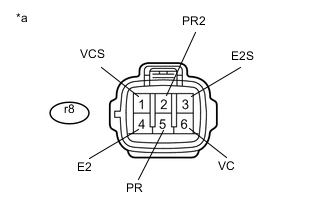
Text in Illustration *a Front view of wire harness connector
(to Fuel Pressure Sensor)
Disconnect the fuel pressure sensor connector.
-
Measure the resistance according to the value(s) in the table below.
Standard Resistance Tester Connection Condition Specified Condition r8-6 (VC) - r8-5 (PR) Engine switch off No short or open circuit r8-5 (PR) - r8-4 (E2) Engine switch off No short or open circuit r8-1 (VCS) - r8-2 (PR2) Engine switch off No short or open circuit r8-2 (PR2) - r8-3 (E2S) Engine switch off No short or open circuit -
Reconnect the fuel pressure sensor connector.
OK
REPLACE COMMON RAIL ASSEMBLY (FUEL PRESSURE SENSOR) Click here
NG
-
-
REPLACE ECM
-
Replace the ECM Click here.
NEXT
CONFIRM WHETHER MALFUNCTION HAS BEEN SUCCESSFULLY REPAIRED Click here
-
-
REPAIR OR REPLACE HARNESS OR CONNECTOR
-
Repair or replace the harness or connector.
NEXT
CONFIRM WHETHER MALFUNCTION HAS BEEN SUCCESSFULLY REPAIRED Click here
-
-
REPLACE COMMON RAIL ASSEMBLY (FUEL PRESSURE SENSOR)
-
Replace the common rail assembly Click here.
NEXT
-
-
BLEED AIR FROM FUEL SYSTEM
-
Bleed the air from the fuel system Click here.
NEXT
-
-
CONFIRM WHETHER MALFUNCTION HAS BEEN SUCCESSFULLY REPAIRED
-
Connect the GTS to the DLC3.
-
Clear the DTCs Click here.
-
Turn the engine switch off for 30 seconds or more.
-
Turn the engine switch on (IG) and turn the GTS on.
-
Let the engine idle for 60 seconds, and then quickly increase the engine speed to 2500 rpm repeatedly for 30 seconds.
-
Confirm that the DTC is not output again.
Tech Tips
Perform the following procedure using the GTS to determine whether or not the DTC judgment has been carried out.
-
Enter the following menus: Powertrain / Engine and ECT / Utility / All Readiness.
-
Input DTC P0087.
-
Check that STATUS is NORMAL. If STATUS is INCOMPLETE or N/A, increase the idling time.
-
NEXT
END
-