ECD SYSTEM(w/ Urea SCR System), Diagnostic DTC:P0016, P0340
| DTC Code | DTC Name |
|---|---|
| P0016 | Crankshaft Position - Camshaft Position Correlation (Bank 1 Sensor A) |
| P0340 | Camshaft Position Sensor Circuit |
DESCRIPTION
The camshaft position sensor (G2 signal) consists of a magnet and MRE (Magneto Resistance Element).
The G2 signal plate has 3 teeth on its outer circumference and is installed on the exhaust camshaft. When the camshaft rotates, the protrusion on the signal plate and the air gap on the MRE change, causing fluctuations in the magnetic field that generate a voltage in the MRE.
The NE signal plate has 34 teeth and is mounted on the crankshaft angle sensor plate. The NE signal sensor generates 34 signals for every revolution. The ECM detects the camshaft angle based on the G2 signal, and detects the crankshaft angle based on the NE signal.
| DTC Detection Drive Pattern | DTC Detection Condition | Trouble Area |
|---|---|---|
| Idle engine for 5 seconds or more | Phase deviation in crankshaft and camshaft position sensor signals with an engine speed of 650 to 3000 rpm occurs a certain number of times. (1 trip detection logic) |
|
| DTC Detection Drive Pattern | DTC Detection Condition | Trouble Area |
|---|---|---|
| Crank engine for 4 seconds | STA on: No camshaft position sensor signal is sent to the ECM while cranking for 4 seconds or more. (2 trip detection logic) |
|
| Idle engine for 1 second or more | STA off: Camshaft position sensor signal is not input with an engine speed of 650 rpm or more. (1 trip detection logic) |
Tech Tips
-
If DTC P0016 or P0340 is stored, the following symptoms may appear:
-
Difficulty starting
-
Misfire
-
Combustion noise
-
Black smoke
-
White smoke
-
Lack of power
Reference: Inspection using an oscilloscope.
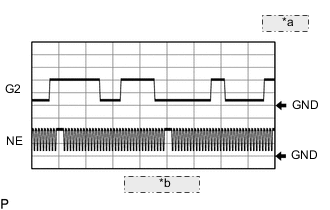
| *a | 2 V/DIV. |
| *b | 20 msec./DIV. |
Tech Tips
The correct waveform is as shown.
| ECM Terminal Name | Between G2+ and G2- Between NE+ and NE- |
| Tester Range | 2 V/DIV., 20 msec./DIV. |
| Condition | Idling after engine warmed |
WIRING DIAGRAM
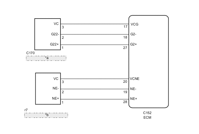
| *a | Camshaft Position Sensor |
| *b | Crankshaft Position Sensor |
CAUTION / NOTICE / HINT
Note
After replacing the ECM, the new ECM needs registration (See page ) and initialization Click here.
Tech Tips
Read freeze frame data using the GTS. Freeze frame data records the engine condition when malfunctions are detected. When troubleshooting, freeze frame data can help determine if the vehicle was moving or stationary, if the engine was warmed up or not, and other data from the time the malfunction occurred.
PROCEDURE
-
CHECK ENGINE CRANKING CONDITION
-
Check the engine cranking condition.
Result Result Proceed to Cranking is OK A Does not crank at all B
B 
GO TO PROBLEM SYMPTOMS TABLE Click here
A 
-
-
INSPECT ECM TERMINAL VOLTAGE (CAMSHAFT POSITION SENSOR)
-
Inspect the ECM using an oscilloscope.
-
While the engine is idling, check the waveform between the terminals of the ECM connector.
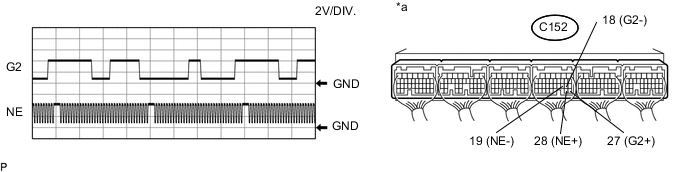
Text in Illustration *a Component with harness connected
(ECM)
- - OK Tester Connection Tester Range Condition Specified Condition C152-27 (G2+) - C152-18 (G2-) 2 V/DIV.
20 msec./DIV.
Idling Correct waveform as shown in illustration C152-28 (NE+) - C152-19 (NE-) 2 V/DIV.
20 msec./DIV.
Idling Correct waveform as shown in illustration
-
NG 
CHECK CAMSHAFT POSITION SENSOR (SENSOR INSTALLATION) Click here
OK
-
-
INSPECT CAMSHAFT POSITION SENSOR AND CRANKSHAFT POSITIONSENSOR TIMING
-
Inspect the ECM using an oscilloscope.
-
While the engine is idling, check the waveform between the terminals of the ECM connector.
-
Inspect the camshaft position sensor and crankshaft position sensor timing.
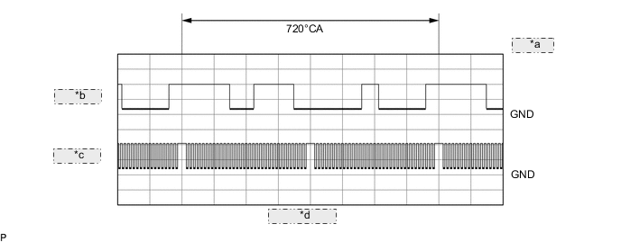
*a 2 V/DIV. *b G2 Signal *c Ne Signal *d 20 msec./DIV. OK Tester Connection Tester Range Condition Specified Condition C152-27 (G2+) - C152-18 (G2-) 2 V/DIV.
20 msec./DIV.
Idling Correct waveform as shown in illustration C152-28 (NE+) - C152-19 (NE-) 2 V/DIV.
20 msec./DIV.
Idling Correct waveform as shown in illustration
NG
CHECK ENGINE MECHANICAL SYSTEM Click here
OK
-
-
CHECK WHETHER DTC OUTPUT RECURS
-
Connect the GTS to the DLC3.
-
Turn the engine switch on (IG) and turn the GTS on.
-
Clear the DTCs Click here.
-
Turn the engine switch off for 30 seconds or more.
-
Start the engine and idle it for 5 seconds or more.
-
Enter the following menus: Powertrain / Engine and ECT / Trouble Codes.
-
Read the DTCs.
Result Result Proceed to DTC P0016 or P0340 is output A DTC is not output B
B
CHECK FOR INTERMITTENT PROBLEMS Click here
A
-
-
REPLACE ECM
-
Replace the ECM Click here.
NEXT
CONFIRM WHETHER MALFUNCTION HAS BEEN SUCCESSFULLY REPAIRED Click here
-
-
CHECK ENGINE MECHANICAL SYSTEM
-
When the G2 signal appears to be malfunctioning, check the exhaust camshaft.
-
If the teeth of the timing rotor are damaged, perform replacement Click here.
-
-
When the Ne signal appears to be malfunctioning, check the following parts.
-
Installation condition of the crankshaft position sensor.
-
Crank angle sensor plate.
-
-
Check for mechanical malfunctions that affect the valve timing, such as a jumped tooth or stretching of the timing chain Click here.
NEXT
CONFIRM WHETHER MALFUNCTION HAS BEEN SUCCESSFULLY REPAIRED Click here
-
-
CHECK CAMSHAFT POSITION SENSOR (SENSOR INSTALLATION)
-
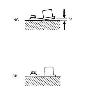
Text in Illustration *a Clearance Check the sensor installation.
OK Camshaft position sensor is installed correctly.
NG
SECURELY REINSTALL CAMSHAFT POSITION SENSOR Click here
OK
-
-
INSPECT EXHAUST CAMSHAFT (TIMING ROTOR)
-
Inspect the timing rotor of the exhaust camshaft.
OK Camshaft timing rotor does not have any cracks or deformation.
NG
REPLACE EXHAUST CAMSHAFT Click here
OK
-
-
REPLACE CAMSHAFT POSITION SENSOR
-
Replace the camshaft position sensor Click here.
NEXT
CONFIRM WHETHER MALFUNCTION HAS BEEN SUCCESSFULLY REPAIRED Click here
-
-
REPLACE EXHAUST CAMSHAFT
-
Replace the exhaust camshaft.
NEXT
CONFIRM WHETHER MALFUNCTION HAS BEEN SUCCESSFULLY REPAIRED Click here
-
-
SECURELY REINSTALL CAMSHAFT POSITION SENSOR
-
Securely reinstall the camshaft position sensor.
NEXT
-
-
CONFIRM WHETHER MALFUNCTION HAS BEEN SUCCESSFULLY REPAIRED
-
Connect the GTS to the DLC3.
-
Turn the engine switch on (IG) and turn the GTS on.
-
Clear the DTCs Click here.
-
Turn the engine switch off for 30 seconds or more.
-
Start the engine and idle it for 5 seconds or more.
-
Enter the following menus: Powertrain / Engine and ECT / Trouble Codes.
-
Confirm that the DTC is not output.
NEXT
END
-