ECD SYSTEM VC Output Circuit
DESCRIPTION
The ECM constantly generates a 5 V power source voltage from the battery voltage supplied to the +B (BATT) terminal to operate the microprocessor. The ECM also provides this power source voltage to the sensors through the VC output circuit.
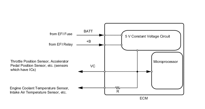
When the VC circuit has a short circuit, the CPU in the ECM and sensors that are supplied power through the VC circuit are deactivated because power is not supplied from the VC circuit. When the system is in this condition, it will not start.
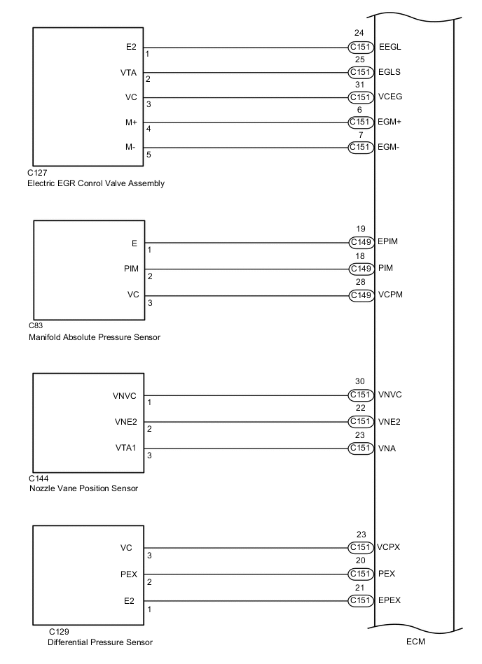
WIRING DIAGRAM
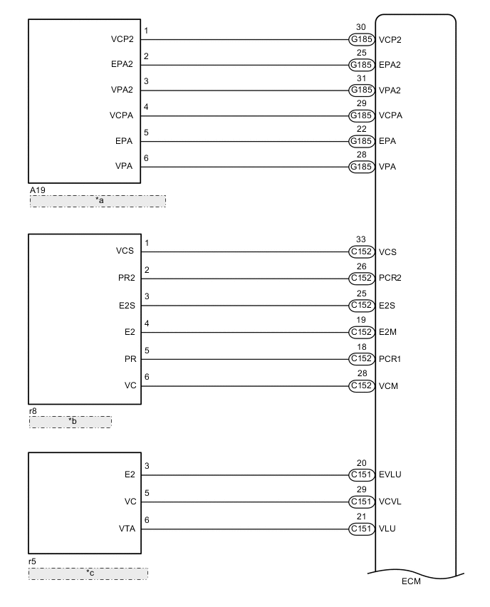
| *a | Accelerator Pedal Position Sensor |
| *b | Fuel Pressure Sensor |
| *c | Diesel Throttle Body Assembly |
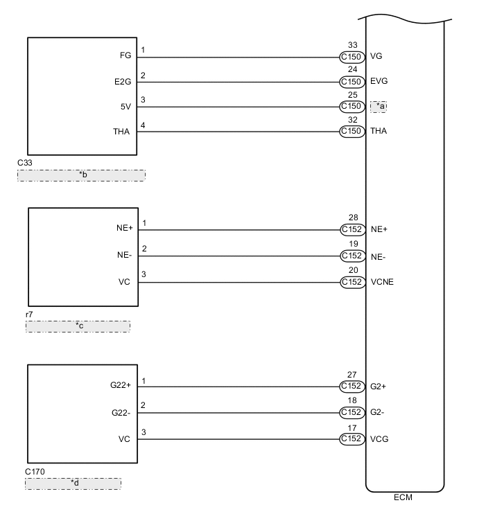
| *a | VCVG |
| *b | Mass Air Flow Meter Sub-assembly |
| *c | Crankshaft Position Sensor |
| *d | Camshaft Position Sensor |
CAUTION / NOTICE / HINT
Note
After replacing the ECM, the new ECM needs registration (See page ) and initialization Click here.
PROCEDURE
-
CHECK MIL
-
Check that the Malfunction Indicator Lamp (MIL) lights up when the engine switch is turned on (IG).
Result Result Proceed to MIL does not illuminate A MIL illuminates B
B 
PROCEED TO NEXT SUSPECTED AREA SHOWN IN PROBLEM SYMPTOMS TABLE Click here
A 
-
-
CHECK COMMUNICATION BETWEEN GTS AND ECM
-
Connect the GTS to the DLC3.
-
Turn the engine switch on (IG) and turn the GTS on.
-
Check the communication between the GTS and ECM.
Result Result Proceed to Communication is not possible A Communication is possible B
B
GO TO MIL CIRCUIT Click here
A
-
-
CHECK MIL (DIESEL THROTTLE BODY ASSEMBLY)
-
Disconnect the diesel throttle body assembly connector.
-
Turn the engine switch on (IG).
-
Check the MIL.
Result Result Proceed to MIL does not illuminate A MIL illuminates B -
Reconnect the diesel throttle body assembly connector.
B
REPLACE DIESEL THROTTLE BODY ASSEMBLY Click here
A
-
-
CHECK MIL (ACCELERATOR PEDAL POSITION SENSOR)
-
Disconnect the accelerator pedal position sensor connector.
-
Turn the engine switch on (IG).
-
Check the MIL.
Result Result Proceed to MIL does not illuminate A MIL illuminates B -
Reconnect the accelerator pedal position sensor connector.
B
REPLACE ACCELERATOR PEDAL SENSOR ASSEMBLY Click here
A
-
-
CHECK MIL (FUEL PRESSURE SENSOR)
-
Disconnect the fuel pressure sensor connector.
-
Turn the engine switch on (IG).
-
Check the MIL.
Result Result Proceed to MIL does not illuminate A MIL illuminates B -
Reconnect the fuel pressure sensor connector.
B
REPLACE COMMON RAIL ASSEMBLY Click here
A
-
-
CHECK MIL (MANIFOLD ABSOLUTE PRESSURE SENSOR)
-
Disconnect the manifold absolute pressure sensor connector.
-
Turn the engine switch on (IG).
-
Check the MIL.
Result Result Proceed to MIL does not illuminate A MIL illuminates B -
Reconnect the manifold absolute pressure sensor connector.
B
REPLACE MANIFOLD ABSOLUTE PRESSURE SENSOR Click here
A
-
-
CHECK MIL (ELECTRIC EGR CONTROL VALVE ASSEMBLY)
-
Disconnect the electric EGR control valve assembly connector.
-
Turn the engine switch on (IG).
-
Check the MIL.
Result Result Proceed to MIL does not illuminate A MIL illuminates B -
Reconnect the electric EGR control valve assembly connector.
B
REPLACE ELECTRIC EGR CONTROL VALVE ASSEMBLY Click here
A
-
-
CHECK MIL (DIFFERENTIAL PRESSURE SENSOR)
-
Disconnect the differential pressure sensor connector.
-
Turn the engine switch on (IG).
-
Check the MIL.
Result Result Proceed to MIL does not illuminate A MIL illuminates B -
Reconnect the differential pressure sensor connector.
B
REPLACE DIFFERENTIAL PRESSURE SENSOR Click here
A
-
-
CHECK MIL (NOZZLE VANE POSITION SENSOR)
-
Disconnect the nozzle vane position sensor connector.
-
Turn the engine switch on (IG).
-
Check the MIL.
Result Result Proceed to MIL does not illuminate A MIL illuminates B -
Reconnect the nozzle vane position sensor connector.
B
REPLACE TURBOCHARGER NOZZLE VANE CONTROL ACTUATOR Click here
A
-
-
CHECK MIL (MASS AIR FLOW METER SUB-ASSEMBLY)
-
Disconnect the mass air flow meter sub-assembly connector.
-
Turn the engine switch on (IG).
-
Check the MIL.
Result Result Proceed to MIL does not illuminate A MIL illuminates B -
Reconnect the mass air flow meter sub-assembly connector.
B
REPLACE MASS AIR FLOW METER SUB-ASSEMBLY Click here
A
-
-
CHECK MIL (CAMSHAFT POSITION SENSOR)
-
Disconnect the camshaft position sensor connector.
-
Turn the engine switch on (IG).
-
Check the MIL.
Result Result Proceed to MIL does not illuminate A MIL illuminates B -
Reconnect the camshaft position sensor connector.
B
REPLACE CAMSHAFT POSITION SENSOR Click here
A
-
-
CHECK MIL (CRANKSHAFT POSITION SENSOR)
-
Disconnect the crankshaft position sensor connector.
-
Turn the engine switch on (IG).
-
Check the MIL.
Result Result Proceed to MIL does not illuminate A MIL illuminates B -
Reconnect the crankshaft position sensor connector.
B
REPLACE CRANKSHAFT POSITION SENSOR Click here
A
-
-
CHECK HARNESS AND CONNECTOR
-
Disconnect the diesel throttle body assembly connector.
-
Disconnect the accelerator pedal position sensor connector.
-
Disconnect the fuel pressure sensor connector.
-
Disconnect the manifold absolute pressure sensor connector.
-
Disconnect the electric EGR control valve assembly connector.
-
Disconnect the differential pressure sensor connector.
-
Disconnect the nozzle vane position sensor connector.
-
Disconnect the mass air flow meter sub-assembly connector.
-
Disconnect the camshaft position sensor connector.
-
Disconnect the crankshaft position sensor connector.
-
Disconnect the ECM connectors.
-
Measure the resistance according to the value(s) in the table below.
Standard Resistance Tester Connection Condition Specified Condition C151-29 (VCVL) - Body ground and other terminals Always 10 kΩ or higher G185-29 (VCPA) - Body ground and other terminals Always 10 kΩ or higher G185-30 (VCP2) - Body ground and other terminals Always 10 kΩ or higher C151-28 (VCM) - Body ground and other terminals Always 10 kΩ or higher C149-28 (VCPM) - Body ground and other terminals Always 10 kΩ or higher C151-31 (VCEG) - Body ground and other terminals Always 10 kΩ or higher C151-32 (VCPX) - Body ground and other terminals Always 10 kΩ or higher C151-30 (VNVC) - Body ground and other terminals Always 10 kΩ or higher C150-25 (VCVG) - Body ground and other terminals Always 10 kΩ or higher C152-17 (VCG) - Body ground and other terminals Always 10 kΩ or higher C152-20 (VCNE) - Body ground and other terminals Always 10 kΩ or higher -
Reconnect the diesel throttle body assembly connector.
-
Reconnect the accelerator pedal position sensor connector.
-
Reconnect the fuel pressure sensor connector.
-
Reconnect the manifold absolute pressure sensor connector.
-
Reconnect the electric EGR control valve assembly connector.
-
Reconnect the differential pressure sensor connector.
-
Reconnect the nozzle vane position sensor connector.
-
Reconnect the mass air flow meter sub-assembly connector.
-
Reconnect the camshaft position sensor connector.
-
Reconnect the crankshaft position sensor connector.
-
Reconnect the ECM connectors.
OK
REPLACE ECM Click here
NG
REPAIR OR REPLACE HARNESS OR CONNECTOR
-