ECD SYSTEM Active Control Engine Mount System
DESCRIPTION
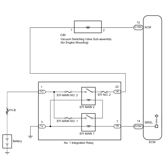
The active control engine mount system decreases engine vibration at low engine speed using the vacuum switching valve sub-assembly (for engine mounting). The vacuum switching valve sub-assembly (for engine mounting) is controlled by a pulse signal transmitted to the vacuum switching valve sub-assembly (for engine mounting) from the ECM. The frequency of this pulse signal is matched to the engine speed to decrease engine vibration.
WIRING DIAGRAM
CAUTION / NOTICE / HINT
Note
-
Inspect the fuses for circuits related to this system before performing the following inspection procedure.
-
After replacing the ECM, the new ECM needs registration (See page ) and initialization Click here.
PROCEDURE
-
INSPECT INTAKE SYSTEM
-
Inspect intake system Click here.
Result Repair any trouble areas.
NG 
REPAIR INTAKE SYSTEM
OK 
-
-
INSPECT VACUUM SWITCHING VALVE SUB-ASSEMBLY (FOR ENGINE MOUNTING) (RESISTANCE)
-
Inspect the vacuum switching valve sub-assembly (for engine mounting) Click here.
NG
REPLACE VACUUM SWITCHING VALVE SUB-ASSEMBLY (FOR ENGINE MOUNTING) Click here
OK
-
-
INSPECT FRONT ENGINE MOUNTING INSULATOR
-
Disconnect the vacuum hose from the front engine mount insulator assembly.
-
Using a vacuum pump, apply vacuum of 80 kPa (600 mmHg, 23.622 in.Hg) and wait for 1 minute.
-
Check that there is no change in the needle movement of the vacuum pump gauge.
-
Check that there is no fluid leakage caused by a break in the diaphragm.
OK Vacuum does not leak. -
Reconnect the vacuum hose.
NG
REPLACE FRONT ENGINE MOUNTING INSULATOR Click here
OK
-
-
INSPECT VACUUM SWITCHING VALVE SUB-ASSEMBLY (FOR ENGINE MOUNTING) (POWER SOURCE VOLTAGE)
-
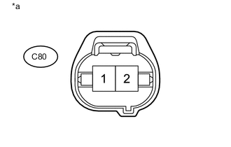
Text in Illustration *1 Front view of wire harness connector
(to Vacuum Switching Valve Sub-assembly (for Engine Mounting))
Disconnect the vacuum switching valve sub-assembly (for engine mounting) connector.
-
Turn the engine switch on (IG).
-
Measure the voltage according to the value(s) in the table below.
Standard Voltage Tester Connection Condition Specified Condition C80-1 - Body ground Engine switch on (IG) 11 to 14 V -
Reconnect the vacuum switching valve sub-assembly (for engine mounting) connector.
NG 
CHECK HARNESS AND CONNECTOR (VACUUM SWITCHING VALVE ASSEMBLY SUB-ASSEMBLY (FOR ENGINE MOUNTING) - NO. 1 INTEGRATION RELAY) Click here
OK
-
-
CHECK HARNESS AND CONNECTOR (VACUUM SWITCHING VALVE SUB-ASSEMBLY (FOR ENGINE MOUNTING) - ECM)
-
Disconnect the vacuum switching valve sub-assembly (for engine mounting) connector.
-
Disconnect the ECM connector.
-
Measure the resistance according to the value(s) in the table below.
Standard Resistance Tester Connection Condition Specified Condition C80-2 - C150-12 (ACM) Always Below 1 Ω C80-2 or C150-12 (ACM) - Body ground and other terminals Always 10 kΩ or higher -
Reconnect the ECM connector.
-
Reconnect the vacuum switching valve sub-assembly (for engine mounting) connector.
OK
REPLACE ECM Click here
NG
REPAIR OR REPLACE HARNESS OR CONNECTOR (VACUUM SWITCHING VALVE SUB-ASSEMBLY(FOR ENGINE MOUNTING) - ECM)
-
-
CHECK HARNESS AND CONNECTOR (VACUUM SWITCHING VALVE ASSEMBLY SUB-ASSEMBLY (FOR ENGINE MOUNTING) - NO. 1 INTEGRATION RELAY)
-
Remove the No. 1 integration relay from the engine room relay block.
-
Disconnect the vacuum switching valve sub-assembly (for engine mounting) connector.
-
Measure the resistance of the wire harness side connectors.
Standard Resistance Tester Connection Condition Specified Condition 1K-22 - C80-1 Always Below 1 Ω K-22 or C80-1 - Body ground and other terminals Always 10 kΩ or higher
NG
REPAIR OR REPLACE HARNESS OR CONNECTOR
OK
-
-
INSPECT NO. 1 INTEGRATION RELAY (EFI MAIN2)
-
Inspect the No. 1 Integration relay (EFI MAIN2) Click here.
OK
INSPECT ECM POWER SOURCE CIRCUIT Click here
NG
REPLACE NO. 1 INTEGRATION RELAY
-