ECD SYSTEM, Diagnostic DTC:P2453
| DTC Code | DTC Name |
|---|---|
| P2453 | Diesel Particulate Filter Pressure Sensor "A" Circuit Range/Performance |
DESCRIPTION
Refer to DTC P2454 Click here.
Tech Tips
-
For more information on the differential pressure sensor and Diesel Particulate Filter (DPF), refer to the following procedures Click here.
-
If P2453 is present, refer to the DTC chart for DPF system Click here.
-
If the vacuum hoses of the differential pressure sensor are incorrectly connected (crossed), the ECM interprets this as an abnormal pressure difference, DTC P2453 (Diesel Particulate Filter Pressure Sensor "A" Circuit Range/Performance) is stored and the MIL illuminates.
| DTC Detection Drive Pattern | DTC Detection Condition | Trouble Area |
|---|---|---|
| Engine is running at 4000 rpm with no load for 10 seconds or more. | When the output voltage from the differential pressure sensor indicates a reversal of positive and negative pressure. (1 trip detection logic) |
|
| DTC No. | Data List |
|---|---|
| P2453 | DPF Differential Pressure |
Tech Tips
-
DTC P2454 (Diesel Particulate Filter Pressure Sensor "A" Circuit Low) and/or DTC P2455 (Diesel Particulate Filter Pressure Sensor "A" Circuit High) will be stored if there is an open or short malfunction in the differential pressure sensor circuit.
-
After confirming DTC P2453, check the differential pressure in "Powertrain / Engine and ECT / Data List / DPF Differential Pressure" using the GTS.
| Condition | DPF Differential Pressure Output | Sensor Condition |
|---|---|---|
| Engine switch on (IG) | Approximately 0 kPa | Normal |
| Always | -5 kPa or less or higher than 99 kPa | Open or short circuit |
| 4000 rpm (No engine load) | Negative output | Incorrect hose routing |
MONITOR DESCRIPTION
In order to detect abnormality in the differential pressure sensor, the ECM always monitors the output voltage from the sensor. When the sensor output voltage is a reversal of positive and negative pressure, the ECM interprets this as an incorrect vacuum hose arrangement of the sensor, or determines that the vacuum hoses are clogged, and illuminates the MIL.
CAUTION / NOTICE / HINT
Note
After replacing the ECM, the new ECM needs registration (See page ) and initialization Click here.
Tech Tips
Read freeze frame data using the GTS. Freeze frame data records the engine condition when malfunctions are detected. When troubleshooting, freeze frame data can help determine if the vehicle was moving or stationary, if the engine was warmed up or not, and other data from the time the malfunction occurred.
PROCEDURE
-
CHECK OTHER DTC OUTPUT (IN ADDITION TO DTC P2453)
-
Connect the GTS to the DLC3.
-
Turn the engine switch on (IG) and turn the GTS on.
-
Enter the following menus: Powertrain / Engine and ECT / Trouble Codes.
-
Read the DTCs.
Result Result Proceed to DTC P2453 is output A DTC P2453 and other DTCs are output B Tech Tips
If codes other than P2453 are output, perform troubleshooting for those DTCs first.
B 
GO TO DTC CHART Click here
A 
-
-
CHECK CONNECTION OF AIR HOSE (DIFFERENTIAL PRESSURE SENSOR - VACUUM PIPE)
-
Check if the air hose routing between the differential pressure sensor and vacuum pipe is correct Click here.
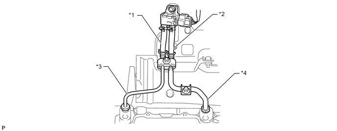
Text in Illustration *1 Air Hose (Downstream) *2 Air Hose (Upstream) *3 No. 2 Vacuum Pipe *4 No. 1 Vacuum Pipe -
Check that there is no exhaust gas leakage between the differential pressure sensor and vacuum pipe.
NG 
CORRECT TO NORMAL CONNECTION Click here
OK
-
-
CHECK BLOCKAGE OF AIR HOSE AND VACUUM PIPE
CAUTION:
Be careful of being burned by exhaust gases during the following inspection.
-
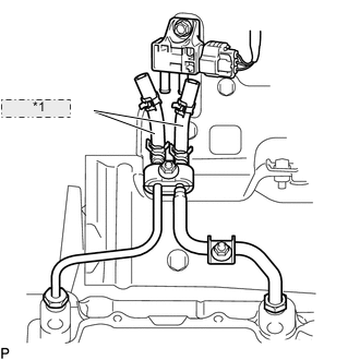
*1 Vacuum Hose Disconnect the air hoses (both upstream and downstream) from the differential pressure sensor.
-
Start the engine.
-
Check if there are exhaust gas pulsations from both air hoses during idling.
OK Exhaust gas pulsation exists.
NG
REPLACE CLOGGED PARTS Click here
OK
-
-
READ VALUE USING GTS (DPF DIFFERENTIAL PRESSURE)
-
Connect the GTS to the DLC3.
-
Turn the engine switch on (IG) and turn the GTS on.
-
Enter the following menus: Powertrain / Engine and ECT / Data List / DPF Differential Pressure.
-
Check that the differential pressure is as specified below.
Result Condition Differential Pressure Output Sensor Condition Engine switch on (IG) Approximately 0 kPa Normal
OK
CONFIRM WHETHER MALFUNCTION HAS BEEN SUCCESSFULLY REPAIRED Click here
NG
REPLACE DIFFERENTIAL PRESSURE SENSOR Click here
-
-
CORRECT TO NORMAL CONNECTION
NEXT
CONFIRM WHETHER MALFUNCTION HAS BEEN SUCCESSFULLY REPAIRED Click here
-
REPLACE CLOGGED PARTS
NEXT
CONFIRM WHETHER MALFUNCTION HAS BEEN SUCCESSFULLY REPAIRED Click here
-
REPLACE DIFFERENTIAL PRESSURE SENSOR
-
Replace the differential pressure sensor Click here.
NEXT
-
-
CONFIRM WHETHER MALFUNCTION HAS BEEN SUCCESSFULLY REPAIRED
-
Connect the GTS to the DLC3.
-
Turn the engine switch on (IG) and turn the GTS on.
-
Clear the DTCs Click here.
-
Turn the engine switch off for 30 seconds or more.
-
Turn the engine switch on (IG) and turn the GTS on.
-
Enter the following menus: Powertrain / Engine and ECT / Data List / DPF Differential Pressure.
-
Check that the differential pressure is as specified below.
Tech Tips
-
As long as the pipe connections are correct, the displayed pressure will not be vacuum pressure.
-
For reference result of real-vehicle check is as shown in the table below:
Condition DPF Differential Pressure 2500 rpm without load 0.5 kPa or more
-
-
Start the engine.
-
Engine is running at 4000 rpm with no load for 10 seconds or more.
-
Confirm that the DTC is not output again.
Tech Tips
Perform the following procedure using the GTS to determine whether or not the DTC judgment has been carried out.
-
Enter the following menus: Powertrain / Engine and ECT / Utility / All Readiness.
-
Input DTC P2453.
-
Check that STATUS is NORMAL. If STATUS is INCOMPLETE or N/A, run the engine at 4000 rpm with no load for 10 seconds or more.
-
NEXT
END
-