ECD SYSTEM Lack of Power (Turbocharger System)
CAUTION / NOTICE / HINT
Tech Tips
-
The diagnosis flowchart is for lack of power due to turbocharger factors.
-
If symptom-specific diagnosis indicates a turbocharger related problem, check using this flowchart.
PROCEDURE
-
CHECK TURBOCHARGER SUB-ASSEMBLY
-
Check that no soot or oil adheres to the turbocharger sub-assembly connectors.
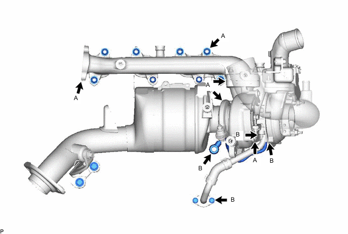
Tech Tips
If adhering soot or an oil leak exists, air leaking at that position may be the cause of the lack of boost pressure.
Result: Result Proceed to No adhering soot or an oil A Soot adhering around the turbine housing, flange, or V band (A in the illustration) B Oil leak from the contact surface between the compressor housing and bearing housing (B in the illustration) C
B 
CHECK EXHAUST MANIFOLD CONVERTER SUB-ASSEMBLY Click here
C 
REPLACE TURBOCHARGER SUB-ASSEMBLY Click here
A 
-
-
INSPECT TURBOCHARGER SUB-ASSEMBLY (TURBINE SHAFT)
-
Remove the turbocharger sub-assembly.
-
Check that the turbine shaft rotates smoothly, without catching.
-
Check for loose turbine mounting nuts and for axial play in the turbine shaft.
Tech Tips
If the turbine shaft catches or if there is no play or excessive play, it could indicate improper sealing due to seizing or poor sliding because of a deposit build-up.
Standard value 0.10 mm (0.00394 in.) or less
Result: Result Proceed to No turbine shaft malfunction A Turbine shaft malfunction B -
B
REPLACE TURBOCHARGER SUB-ASSEMBLY Click here
A
-
-
INSPECT TURBOCHARGER SUB-ASSEMBLY
-
Check for interference between the turbine wheel and the turbine housing.
Tech Tips
When there is interference between the turbine wheel and turbine housing and the turbine wheel is damaged, check for fragments of the turbine wheel in the exhaust manifold converter subassembly.
Result: Result Proceed to No damage or interference A Damage or interference exists B
B
REPLACE TURBOCHARGER SUB-ASSEMBLY Click here
A
-
-
INSPECT TURBOCHARGER NOZZLE VANE PLATE
-
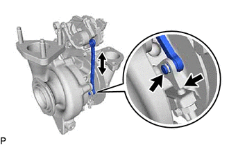
Inspect the turbocharger nozzle vane plate.
-
Remove the e-washer from the turbocharger nozzle vane control actuator.
-
-
Move the turbocharger vane control rod subassembly and check that the turbocharger nozzle vane plate moves.
Result: Result Proceed to Catches, but operates* A Gets stuck and does not operate B Tech Tips
*: Check several times.
OK
REPLACE TURBOCHARGER NOZZLE VANE CONTROL ACTUATOR Click here
NG
REPLACE TURBOCHARGER SUB-ASSEMBLY Click here
-
-
CHECK EXHAUST MANIFOLD CONVERTER SUB-ASSEMBLY
-
Check for deformation or cracks in the mounting surfaces on the exhaust manifold converter subassembly and the turbocharger sub-assembly.
Tech Tips
Deformation or cracks on a mounting surface may allow exhaust gas to leak from the damaged position.
Standard No deformation or cracks on a mounting surface Result: Result Proceed to No problem with the mounting surface A Deformation or cracks on the exhaust manifold converter sub-assembly mounting surface B Deformation or cracks on the turbocharger subassembly mounting surface C
B
REPLACE EXHAUST MANIFOLD CONVERTER SUB-ASSEMBLY Click here
C
REPLACE TURBOCHARGER SUB-ASSEMBLY Click here
A
-
-
REPLACE EXHAUST CLANP AND GASKET
-
Replace the exhaust clamp and the gasket.
NEXT
-
-
PERFORM SIMULATION TEST
-
Check that the abnormal state has disappeared.
NEXT
END
-