ECD SYSTEM Starter Signal Circuit
DESCRIPTION
While the engine is being cranked, the starter signal is also sent to terminal STA of the ECM.
The starter signal mainly performs engine control when the engine is started.
WIRING DIAGRAM
Refer to DTC P0617 Click here.
CAUTION / NOTICE / HINT
Note
-
Inspect the fuses of circuits related to this system before performing the following inspection procedure.
-
After replacing the ECM, the new ECM needs registration (See page ) and initialization Click here.
Tech Tips
This chart is based on the premise that the engine can crank normally. If the engine cannot crank normally, proceed to Problem Symptoms Table Click here.
PROCEDURE
-
CHECK WHETHER ENGINE CAN BE CRANKED
-
Check if the engine can be cranked.
Result Result Proceed to Engine cannot be cranked A Engine can be cranked B
B 
READ VALUE USING GTS (STARTER SIGNAL) Click here
A 
-
-
READ VALUE USING GTS (STARTER SIGNAL)
-
Connect the GTS to the DLC3.
-
Turn the engine switch to on (IG).
-
Turn the GTS on.
-
Enter the following menus: Powertrain / Engine and ECT / Data List / Starter Signal.
-
Check the value displayed on the GTS when the engine switch is turned to the on (IG) and START positions.
OK Condition GTS Display (Starter Signal) Engine switch on (IG) OFF Engine started ON Result Result Proceed to OK A NG (for automatic transmission models) B NG (for manual transmission models) C
B
INSPECT PARK/NEUTRAL POSITION SWITCH ASSEMBLY Click here
C
INSPECT CLUTCH START SWITCH ASSEMBLY Click here
A
-
-
INSPECT STARTER RELAY (ST)
-
Inspect the starter relay (ST) Click here.
NG 
REPLACE STARTER RELAY (ST)
OK
-
-
INSPECT STARTER ASSEMBLY
-
Inspect the starter assembly.
-
for 2.0 kW type Click here.
-
for 2.7 kW type Click here.
Result Result Proceed to OK A NG (for 2.0 kW type) B NG (for 2.7 kW type) C -
B
REPLACE STARTER ASSEMBLY Click here
C
REPLACE STARTER ASSEMBLY Click here
A
-
-
CHECK HARNESS AND CONNECTOR (STARTER RELAY - STARTER ASSEMBLY)
-
Remove the starter relay (ST) from the engine room relay block.
-
Disconnect the starter assembly connector.
-
Measure the resistance according to the value(s) in the table below.
Standard Resistance (for 2.0 kW type) Tester Connection Condition Specified Condition Starter relay (ST) terminal 3 - D11-1 Always Below 1 Ω Starter relay (ST) terminal 3 or D11-1 - Body ground and other terminals Always 10 kΩ or higher Standard Resistance (for 2.7 kW type) Tester Connection Condition Specified Condition Starter relay (ST) terminal 3 - D10-1 Always Below 1 Ω Starter relay (ST) terminal 3 or D10-1 - Body ground and other terminals Always 10 kΩ or higher -
Reinstall the starter relay.
-
Reconnect the starter assembly connector.
NG
REPAIR OR REPLACE HARNESS OR CONNECTOR
OK
-
-
CHECK TERMINAL VOLTAGE (POWER SOURCE OF STARTER ASSEMBLY)
-
Disconnect the starter assembly connector.
-
Measure the voltage according to the value(s) in the table below.
Standard Voltage (for 2.0 kW type) Tester Connection Condition Specified Condition D8-1 - Body ground Always 11 to 14 V Standard Voltage (for 2.7 kW type) Tester Connection Condition Specified Condition D9-1 - Body ground Always 11 to 14 V -
Reconnect the starter assembly connector.
NG
REPAIR OR REPLACE HARNESS OR CONNECTOR
OK
-
-
CHECK HARNESS AND CONNECTOR (STARTER RELAY - BODY GROUND)
-
Remove the starter relay (ST) from the engine room relay block.
-
Measure the resistance according to the value(s) in the table below.
Standard Resistance Tester Connection Condition Specified Condition Starter relay (ST) terminal 1 - Body ground Always Below 1 Ω Result Result Proceed to OK (for automatic transmission models) A OK (for manual transmission models) B NG C -
Reinstall the starter relay (ST).
B
CHECK HARNESS AND CONNECTOR (CLUTCH START SWITCH ASSEMBLY - CERTIFICATION ECU - STATER RELAY (ST)) Click here
C
REPAIR OR REPLACE HARNESS OR CONNECTOR
A
-
-
CHECK HARNESS AND CONNECTOR (PARK/NEUTRAL POSITION SWITCH ASSEMBLY - CERTIFICATION ECU - STATER RELAY (ST))
-
Remove the starter relay (ST) from the engine room relay block.
-
Disconnect the park/neutral position switch assembly connector.
-
Disconnect the certification ECU (Smart Key ECU Assembly) connector.
-
Measure the resistance according to the value(s) in the table below.
Standard Resistance Tester Connection Condition Specified Condition C159-5 (L) - Starter relay (ST) terminal 2 Always Below 1 Ω G213-12 (STA) - Starter relay (ST) terminal 2 Always Below 1 Ω C159-5 (L) or Starter relay (ST) terminal 2 - Body ground and other terminals Always 10 kΩ or higher G213-12 (STA) or Starter relay (ST) terminal 2 - Body ground and other terminals Always 10 kΩ or higher -
Reinstall the starter relay (ST).
-
Reconnect the park/neutral position switch assembly connector.
-
Reconnect the certification ECU (Smart Key ECU Assembly) connector.
OK
CHECK TERMINAL VOLTAGE (POWER SOURCE OF STARTER RELAY (ST)) Click here
NG
REPAIR OR REPLACE HARNESS OR CONNECTOR
-
-
CHECK HARNESS AND CONNECTOR (CLUTCH START SWITCH ASSEMBLY - CERTIFICATION ECU - STATER RELAY (ST))
-
Remove the starter relay (ST) from the engine room relay block.
-
Disconnect the clutch start switch assembly connector.
-
Disconnect the certification ECU (Smart Key ECU Assembly) connector.
-
Measure the resistance according to the value(s) in the table below.
Standard Resistance (for LHD) Tester Connection Condition Specified Condition A40-1 - Starter relay (ST) terminal 2 Always Below 1 Ω G213-12 (STA) - Starter relay (ST) terminal 2 Always Below 1 Ω A40-1 or Starter relay (ST) terminal 2 - Body ground and other terminals Always 10 kΩ or higher G213-12 (STA) or Starter relay (ST) terminal 2 - Body ground and other terminals Always 10 kΩ or higher Standard Resistance (for RHD) Tester Connection Condition Specified Condition r1-1 - Starter relay (ST) terminal 2 Always Below 1 Ω G213-12 (STA) - Starter relay (ST) terminal 2 Always Below 1 Ω r1-1 or Starter relay (ST) terminal 2 - Body ground and other terminals Always 10 kΩ or higher G213-12 (STA) or Starter relay (ST) terminal 2 - Body ground and other terminals Always 10 kΩ or higher -
Reinstall the starter relay.
-
Reconnect the the clutch start switch assembly connector.
-
Reconnect the certification ECU (Smart Key ECU Assembly) connector.
NG
REPAIR OR REPLACE HARNESS OR CONNECTOR
OK
-
-
CHECK TERMINAL VOLTAGE (POWER SOURCE OF STARTER RELAY (ST))
-
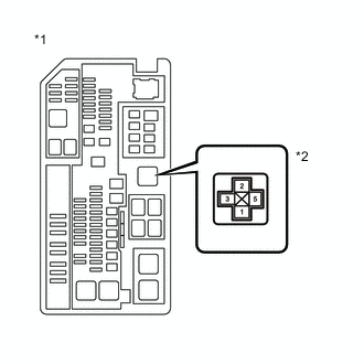
Text in Illustration *1 Engine Room Relay Block *2 Starter Relay (ST) Remove the starter relay (ST) from the engine room relay block.
-
Measure the voltage according to the value(s) in the table below.
Standard Voltage Tester Connection Condition Specified Condition Starter relay (ST) terminal 5 - Body ground Always 11 to 14 V -
Reinstall the starter relay (ST).
OK
CHECK ENTRY AND START SYSTEM Click here
NG
REPAIR OR REPLACE HARNESS OR CONNECTOR (BATTERY - STARTER RELAY)
-
-
INSPECT PARK/NEUTRAL POSITION SWITCH ASSEMBLY
-
Inspect the park/neutral position switch assembly Click here.
NG
REPLACE PARK/NEUTRAL POSITION SWITCH ASSEMBLY Click here
OK
-
-
CHECK HARNESS AND CONNECTOR (ECM - CERTIFICATION ECU - PARK/NEUTRAL POSITION SWITCH ASSEMBLY - STATER RELAY (ST))
-
Remove the starter relay (ST) from the engine room relay block.
-
Disconnect the park/neutral position switch assembly connector.
-
Disconnect the certification ECU (Smart Key ECU Assembly) connector.
-
Measure the resistance according to the value(s) in the table below.
Standard Resistance Tester Connection Condition Specified Condition C159-5 (L) - Starter relay (ST) terminal 2 Always Below 1 Ω G213-12 (STA) - Starter relay (ST) terminal 2 Always Below 1 Ω C159-5 (L) or Starter relay (ST) terminal 2 - Body ground and other terminals Always 10 kΩ or higher G213-12 (STA) or Starter relay (ST) terminal 2 - Body ground and other terminals Always 10 kΩ or higher -
Reinstall the starter relay.
-
Reconnect the park/neutral position switch assembly connector.
-
Reconnect the certification ECU (Smart Key ECU Assembly) connector.
NG
REPAIR OR REPLACE HARNESS OR CONNECTOR
OK
-
-
CHECK HARNESS AND CONNECTOR (PARK/NEUTRAL POSITION SWITCH ASSEMBLY - CERTIFICATION ECU - ECM)
-
Disconnect the ECM connector.
-
Disconnect the park/neutral position switch assembly connector.
-
Disconnect the certification ECU (Smart Key ECU Assembly) connector.
-
Measure the resistance according to the value(s) in the table below.
Standard Resistance Tester Connection Condition Specified Condition C159-4 (B) - G213-10 (STAR) Always Below 1 Ω G213-10 (STAR) - G184-11 (NSW) Always Below 1 Ω C159-4 (B) or G213-10 (STAR) - Body ground and other terminals Always 10 kΩ or higher G213-10 (STAR) or G184-11 (NSW) - Body ground and other terminals Always 10 kΩ or higher -
Reconnect the ECM connector.
-
Reconnect the park/neutral position switch assembly connector.
-
Reconnect the certification ECU (Smart Key ECU Assembly) connector.
OK
CHECK ENTRY AND START SYSTEM Click here
NG
REPAIR OR REPLACE HARNESS OR CONNECTOR
-
-
INSPECT CLUTCH START SWITCH ASSEMBLY
-
Inspect the clutch start switch assembly Click here.
NG
REPLACE CLUTCH START SWITCH ASSEMBLY
OK
-
-
CHECK HARNESS AND CONNECTOR (ECM - CERTIFICATION ECU - CLUTCH START SWITCH ASSEMBLY - STATER RELAY (ST))
-
Remove the starter relay (ST) from the engine room relay block.
-
Disconnect the clutch start switch assembly connector.
-
Disconnect the certification ECU (Smart Key ECU Assembly) connector.
-
Measure the resistance according to the value(s) in the table below.
Standard Resistance (for LHD) Tester Connection Condition Specified Condition C40-1 - Starter relay (ST) terminal 2 Always Below 1 Ω G213-12 (STA) - Starter relay (ST) terminal 2 Always Below 1 Ω C40-1 or Starter relay (ST) terminal 2 - Body ground and other terminals Always 10 kΩ or higher G213-12 (STA) or Starter relay (ST) terminal 2 - Body ground and other terminals Always 10 kΩ or higher Standard Resistance (for RHD) Tester Connection Condition Specified Condition r1-1 - Starter relay (ST) terminal 2 Always Below 1 Ω G213-12 (STA) - Starter relay (ST) terminal 2 Always Below 1 Ω r1-1 or Starter relay (ST) terminal 2 - Body ground and other terminals Always 10 kΩ or higher G213-12 (STA) or Starter relay (ST) terminal 2 - Body ground and other terminals Always 10 kΩ or higher -
Reinstall the starter relay.
-
Reconnect the clutch start switch assembly connector.
-
Reconnect the certification ECU (Smart Key ECU Assembly) connector.
NG
REPAIR OR REPLACE HARNESS OR CONNECTOR
OK
-
-
CHECK HARNESS AND CONNECTOR (CLUTCH START SWITCH ASSEMBLY - CERTIFICATION ECU - ECM)
-
Disconnect the ECM connector.
-
Disconnect the clutch start switch assembly connector.
-
Disconnect the certification ECU (Smart Key ECU Assembly) connector.
-
Measure the resistance according to the value(s) in the table below.
Standard Resistance (for LHD) Tester Connection Condition Specified Condition A40-2 - G213-10 (STAR) Always Below 1 Ω A40-2 or G213-10 (STAR) - Body ground and other terminals Always 10 kΩ or higher Standard Resistance (for RHD) Tester Connection Condition Specified Condition r1-2 - G213-10 (STAR) Always Below 1 Ω r1-2 or G213-10 (STAR) - Body ground and other terminals Always 10 kΩ or higher -
Reconnect the ECM connector.
-
Reconnect the clutch start switch assembly connector.
-
Reconnect the certification ECU (Smart Key ECU Assembly) connector.
OK
CHECK ENTRY AND START SYSTEM Click here
NG
REPAIR OR REPLACE HARNESS OR CONNECTOR
-
-
READ VALUE USING GTS (STARTER SIGNAL)
-
Connect the GTS to the DLC3.
-
Turn the engine switch to on (IG).
-
Turn the GTS on.
-
Enter the following menus: Powertrain / Engine and ECT / Data List / Starter Signal.
-
Check the value displayed on the GTS when the engine switch is turned to the on (IG) and START positions.
OK Condition GTS Display (Starter Signal) Engine switch on (IG) OFF Engine started ON
OK
PROCEED TO NEXT SUSPECTED AREA SHOWN IN PROBLEM SYMPTOMS TABLE Click here
NG
REPAIR OR REPLACE HARNESS OR CONNECTOR (STARTER RELAY - ECM)
-