ECD SYSTEM, Diagnostic DTC:P0201, P0202, P0203, P0204, P062D
| DTC Code | DTC Name |
|---|---|
| P0201 | Injector Circuit / Open - (Cylinder 1) |
| P0202 | Injector Circuit / Open - (Cylinder 2) |
| P0203 | Injector Circuit / Open - (Cylinder 3) |
| P0204 | Injector Circuit / Open - (Cylinder 4) |
| P062D | No. 1 Fuel Injector Driver Circuit Performance |
DESCRIPTION
The injector assemblies are installed in the cylinder head and inject fuel into the cylinders based on the signals from the ECM.
| DTC Detection Drive Pattern | DTC Detection Condition | Trouble Area |
|---|---|---|
| Idling for 5 seconds or more | Open or short in injector circuit occurs a certain number of times (a maximum of approx. 0.5 seconds). (1 trip detection logic) |
|
| DTC Detection Drive Pattern | DTC Detection Condition | Trouble Area |
|---|---|---|
| Idling for 5 seconds or more | ECM internal error (1 trip detection logic) |
ECM |
WIRING DIAGRAM
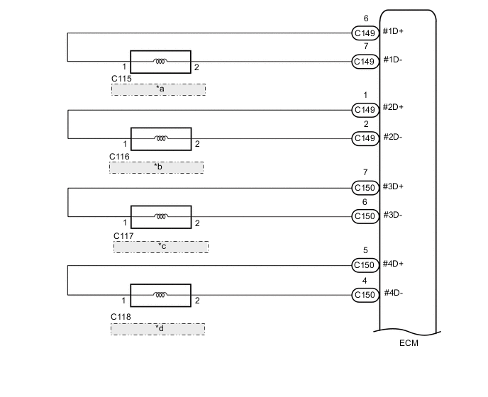
| *a | No. 1 Injector Assembly |
| *b | No. 2 Injector Assembly |
| *c | No. 3 Injector Assembly |
| *d | No. 4 Injector Assembly |
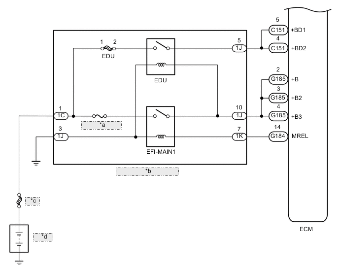
| *a | EFI-MAIN NO. 1 |
| *b | No.1 Integration Relay |
| *c | P/I-B |
| *d | Battery |
CAUTION / NOTICE / HINT
Note
-
Inspect the fuses of circuits related to this system before performing the following inspection procedure.
-
After replacing the ECM, the new ECM needs registration (See page ) and initialization Click here.
-
After replacing an injector assembly, the ECM needs registration Click here.
Tech Tips
Read freeze frame data using the GTS. Freeze frame data records the engine condition when malfunctions are detected. When troubleshooting, freeze frame data can help determine if the vehicle was moving or stationary, if the engine was warmed up or not, and other data from the time the malfunction occurred.
PROCEDURE
-
CHECK DTC OUTPUT
-
Connect the GTS to the DLC3.
-
Turn the engine switch on (IG) and turn the GTS on.
-
Enter the following menus: Powertrain / Engine and ECT / Trouble Codes.
-
Read the DTCs.
Result Result Proceed to DTC P0201, P0202, P0203 or P0204 is output A DTC P062D is output B
A 
CHECK WHETHER DTC OUTPUT RECURS Click here
B 
-
-
INSPECT ECM (+BD1, +BD2 VOLTAGE)
-
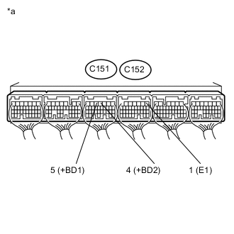
Text in Illustration *a Component with harness connected
(ECD)
Measure the voltage according to the value(s) in the table below.
Standard Voltage Tester Connection Condition Specified Condition C151-5 (+BD1) - C152-1 (E1) Engine switch on (IG) 11 to 14 V C151-4 (+BD2) - C152-1 (E1) Engine switch on (IG) 11 to 14 V
NG
INSPECT NO. 1 INTEGRATION RELAY (EDU) Click here
OK
-
-
REPLACE ECM
-
Replace the ECM Click here.
NEXT
CONFIRM WHETHER MALFUNCTION HAS BEEN SUCCESSFULLY REPAIRED Click here
-
-
INSPECT NO. 1 INTEGRATION RELAY (EDU)
-
Inspect the No. 1 integration relay (EDU) Click here.
NG
REPLACE NO. 1 INTEGRATION RELAY Click here
OK
-
-
REPAIR OR REPLACE HARNESS OR CONNECTOR
-
Repair or replace the harness or connector.
NEXT
CONFIRM WHETHER MALFUNCTION HAS BEEN SUCCESSFULLY REPAIRED Click here
-
-
REPLACE NO. 1 INTEGRATION RELAY
-
Replace the No. 1 integration relay.
NEXT
CONFIRM WHETHER MALFUNCTION HAS BEEN SUCCESSFULLY REPAIRED Click here
-
-
CHECK WHETHER DTC OUTPUT RECURS
-
Connect the GTS to the DLC3.
-
Turn the engine switch on (IG) and turn the GTS on.
-
Clear the DTCs Click here.
-
Turn the engine switch off for 30 seconds.
-
Start the engine and idle it for 30 seconds.
-
Enter the following menus: Powertrain / Engine and ECT / Trouble Codes.
-
Check the DTCs output on the GTS.
Tech Tips
-
The cylinder with the malfunctioning injector assembly can be determined based on the output DTCs.
-
If the DTC P0201 is output, check the No. 1 injector assembly circuit.
-
If the DTC P0202 is output, check the No. 2 injector assembly circuit.
-
If the DTC P0203 is output, check the No. 3 injector assembly circuit.
-
If the DTC P0204 is output, check the No. 4 injector assembly circuit.
-
NEXT
-
-
INSPECT ECM (INJECTION SIGNAL)
-
Disconnect the injector assembly connectors for all cylinders.
Note
If only the injector assembly connector of the malfunctioning cylinder is disconnected, the engine will start and there will be rough idling. Therefore, disconnect all injector assembly connectors before inspecting the waveform.
-
Start the engine.
-
Check the waveform of the injector assembly connectors using an oscilloscope.
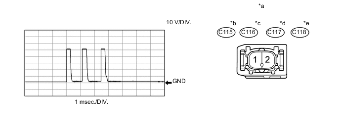
Text in Illustration *a Front view of wire harness connector
(Injector Assembly)
*b No. 1 injector assembly connector *c No. 2 injector assembly connector *d No. 3 injector assembly connector *e No. 4 injector assembly connector - - OK Tester Connection Condition Specified Condition C115-1 - C115-2 Cranking Correct waveform is as shown C116-1 - C116-2 Cranking Correct waveform is as shown C117-1 - C117-2 Cranking Correct waveform is as shown C118-1 - C118-2 Cranking Correct waveform is as shown -
Reconnect the injector assembly connectors for all cylinders.
NG
INSPECT ECM (INJECTION SIGNAL) Click here
OK
-
-
INSPECT INJECTOR ASSEMBLY (RESISTANCE)
-
Inspect the injector assembly of the cylinder relevant to the DTC Click here.
OK 
CHECK FOR INTERMITTENT PROBLEMS Click here
NG
-
-
REPLACE INJECTOR ASSEMBLY (RELEVANT CYLINDER)
-
Replace the injector assembly of the cylinder relevant to the DTC Click here.
Note
-
When replacing the injector assembly for a cylinder, always be sure to use a new No. 1 injection pipe sub-assembly and a new No. 2 injection pipe sub-assembly.
-
Follow the procedure in the repair manual and temporarily install the No. 1 injection pipe sub-assembly, No. 2 injection pipe sub-assembly and No. 1 nozzle leakage pipe assembly pipe, and then correctly position the injector assemblies. After that, tighten parts according to the torque specifications.
-
If the installation procedure is not performed correctly, injector assemblies may become out of position, which may cause the injector assemblies to deteriorate, resulting in malfunctions.
-
If an injector assembly deteriorates and malfunctions, other problems such as knocking, rough idle, etc. may occur.
-
If an injector assembly becomes out of position, it is possible that the seal between the injector assembly and injection pipe sub-assembly may become incomplete, resulting in a fuel leak.
-
NEXT
-
-
BLEED AIR FROM FUEL SYSTEM
-
Bleed the air from the fuel system Click here.
NEXT
-
-
REGISTER INJECTOR COMPENSATION CODE AND PERFORM PILOT QUANTITY LEARNING
-
Register the injector compensation code Click here.
-
Perform the fuel injector pilot quantity learning Click here.
NEXT
CONFIRM WHETHER MALFUNCTION HAS BEEN SUCCESSFULLY REPAIRED Click here
-
-
INSPECT ECM (INJECTION SIGNAL)
-
Disconnect the injector assembly connectors for all cylinders.
Note
If only the injector assembly connector of the malfunctioning cylinder is disconnected, the engine will start and there will be rough idling. Therefore, disconnect all injector assembly connectors before inspecting the waveform.
-
Start the engine.
-
Check the waveform of the injector assembly connectors using an oscilloscope.
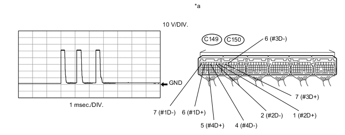
Text in Illustration *a Component with harness connected
(ECM)
- - OK Tester Connection Condition Specified Condition C149-6 (#1D+) - C149-7 (#1D-) Cranking Correct waveform is as shown C149-1 (#2D+) - C149-2 (#2D-) Cranking Correct waveform is as shown C150-7 (#3D+) - C150-6 (#3D-) Cranking Correct waveform is as shown C150-5 (#4D+) - C150-4 (#4D-) Cranking Correct waveform is as shown -
Reconnect the injector assembly connectors for all cylinders.
OK
REPAIR OR REPLACE HARNESS OR CONNECTOR Click here
NG
-
-
REPLACE ECM
-
Replace the ECM Click here.
NEXT
-
-
REPAIR OR REPLACE HARNESS OR CONNECTOR
-
Repair or replace the harness or connector.
NEXT
-
-
CONFIRM WHETHER MALFUNCTION HAS BEEN SUCCESSFULLY REPAIRED
-
Connect the GTS to the DLC3.
-
Clear the DTCs Click here.
-
Turn the engine switch off for 30 seconds or more.
-
Start the engine and idle it for 10 seconds.
-
Enter the following menus: Powertrain / Engine and ECT / Trouble Codes.
-
Confirm that the DTC is not output again.
NEXT
END
-