ECD SYSTEM, Diagnostic DTC:P0122, P0123
| DTC Code | DTC Name |
|---|---|
| P0122 | Throttle / Pedal Position Sensor / Switch "A" Circuit Low Input |
| P0123 | Throttle / Pedal Position Sensor / Switch "A" Circuit High Input |
DESCRIPTION
The throttle position sensor is mounted on the diesel throttle body assembly and detects the opening angle of the throttle valve. This sensor is an electronic sensor and uses Hall-effect elements.
When the throttle valve is fully closed, a voltage of approximately 0.4 to 1.0 V is applied to terminal VLU of the ECM. The voltage applied to terminal VLU of the ECM increases in proportion to the opening angle of the throttle valve and becomes approximately 3.6 to 4.2 V when the throttle valve is fully opened.
The ECM determines the vehicle driving conditions from the signals input to its VLU terminal. The data is one of the pieces of information used for EGR control, etc.
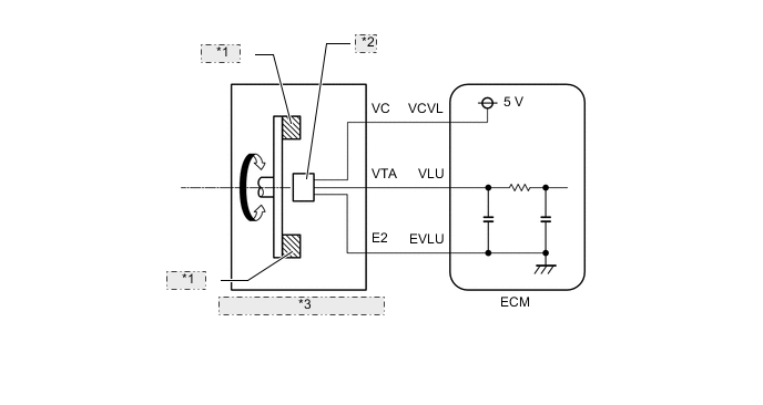
| *1 | Magnet |
| *2 | Hall IC |
| *3 | Throttle Position Sensor |
| DTC Detection Drive Pattern | DTC Detection Condition | Trouble Area |
|---|---|---|
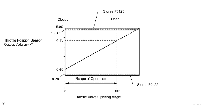
| Engine switch on (IG) for 3 seconds | Throttle position sensor output (VLU) is below 0.2 V for 3 seconds (1 trip detection logic). |
|
| DTC Detection Drive Pattern | DTC Detection Condition | Trouble Area |
|---|---|---|
| Engine switch on (IG) for 3 seconds | Throttle position sensor output (VLU) is higher than 4.8 V for 3 seconds (1 trip detection logic). |
|
Tech Tips
If DTC P0122 and/or P0123 is stored, the following symptoms may appear:
-
- Intake booming noise
-
- Black smoke
-
- Lack of power
-
- Vibration at engine stop
-
- Turbo overspeed, turbo damage
MONITOR DESCRIPTION
When the output voltage of the throttle position sensor deviates from the normal operating range (between 0.2 V and 4.8 V) for more than 3 seconds, the ECM interprets this as a malfunction of the sensor circuit and illuminates the MIL.
WIRING DIAGRAM
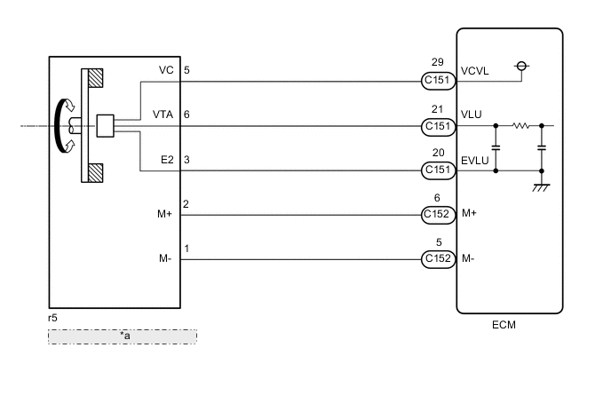
| *a | Diesel Throttle Body Assembly |
CAUTION / NOTICE / HINT
Note
After replacing the ECM, the new ECM needs registration (See page ) and initialization Click here.
Tech Tips
Read freeze frame data using the GTS. Freeze frame data records the engine condition when malfunctions are detected. When troubleshooting, freeze frame data can help determine if the vehicle was moving or stationary, if the engine was warmed up or not, and other data from the time the malfunction occurred.
PROCEDURE
-
CHECK ECM (POWER SOURCE OF THROTTLE POSITION SENSOR)
-
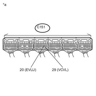
Text in Illustration *a Component with harness connected
(ECM)
Measure the voltage according to the value(s) in the table below.
Standard Voltage Tester Connection Switch Condition Specified Condition C151-29 (VCVL) - C151-20 (EVLU) Engine switch on (IG) 4.5 to 5.5 V
NG 
REPLACE ECM Click here
OK 
-
-
INSPECT THROTTLE POSITION SENSOR VOLTAGE (VLU VOLTAGE)
-
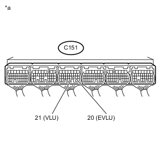
Text in Illustration *a Component with harness connected
(ECM)
Measure the voltage according to the value(s) in the table below.
Standard Voltage Tester Connection Switch Condition Specified Condition C151-21 (VLU) - C151-20 (EVLU) Engine switch on (IG) 3.6 to 4.2 V
NG
CHECK HARNESS AND CONNECTOR Click here
OK
-
-
CHECK DTC OUTPUT
-
Connect the GTS to the DLC3.
-
Clear the DTCs Click here.
-
Turn the engine switch off.
-
Turn the engine switch on (IG) for 3 seconds or more.
-
Enter the following menus: Powertrain / Engine and ECT / Trouble Codes.
-
Read the DTCs.
Result Result Proceed to DTCs are not output A DTC P0122 or P0123 is output B
A 
CHECK FOR INTERMITTENT PROBLEMS Click here
B
REPLACE ECM Click here
-
-
CHECK HARNESS AND CONNECTOR
-
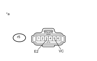
Text in Illustration *a Front view of wire harness connector
(to Diesel Throttle Body Assembly)
Disconnect the diesel throttle body assembly connector.
-
Measure the voltage according to the value(s) in the table below.
Standard Voltage Tester Connection Switch Condition Specified Condition r5-5 (VC) - r5-3 (E2) Engine switch on (IG) 4.5 to 5.5 V -
Reconnect the throttle position sensor connector.
NG
REPAIR OR REPLACE HARNESS OR CONNECTOR Click here
OK
-
-
CHECK HARNESS AND CONNECTOR (THROTTLE POSITION SENSOR - ECM)
-
Disconnect the diesel throttle body assembly connector.
-
Disconnect the ECM connector.
-
Measure the resistance according to the value(s) in the table below.
Standard Resistance Tester Connection Condition Specified Condition r5-6 (VTA) - C151-21 (VLU) Always Below 1 Ω r5-3 (E2) - C151-20 (EVLU) Always Below 1 Ω r5-6 (VTA) or C151-21 (VLU) - Body ground and other terminals Always 10 kΩ or higher r5-3 (E2) or C151-20 (EVLU) - Body ground and other terminals Always 10 kΩ or higher -
Reconnect the diesel throttle body assembly connector.
-
Reconnect the ECM connector.
NG
REPAIR OR REPLACE HARNESS OR CONNECTOR Click here
OK
-
-
CHECK ECM (CHECK RESISTANCE)
-
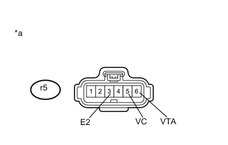
Text in Illustration *a Front view of wire harness connector
(to Diesel Throttle Body Assembly)
Disconnect the diesel throttle body assembly connector.
-
Measure the resistance according to the value(s) in the table below.
Standard Voltage Tester Connection Switch Condition Specified Condition r5-5 (VC) - r5-6 (VTA) Engine switch off No short or open r5-6 (VTA) - r5-3 (E2) -
Reconnect the diesel throttle body assembly connector.
NG
REPLACE ECM Click here
OK
-
-
REPLACE DIESEL THROTTLE BODY ASSEMBLY
-
Replace the diesel throttle body assembly Click here.
NEXT
CONFIRM WHETHER MALFUNCTION HAS BEEN SUCCESSFULLY REPAIRED Click here
-
-
REPLACE ECM
-
Replace the ECM Click here.
NEXT
CONFIRM WHETHER MALFUNCTION HAS BEEN SUCCESSFULLY REPAIRED Click here
-
-
REPAIR OR REPLACE HARNESS OR CONNECTOR
-
Repair or replace the harness or connector.
NEXT
-
-
CONFIRM WHETHER MALFUNCTION HAS BEEN SUCCESSFULLY REPAIRED
-
Connect the GTS to the DLC3.
-
Clear the DTCs Click here.
-
Turn the engine switch off.
-
Turn the engine switch on (IG) for 3 seconds.
-
Enter the following menus: Powertrain / Engine and ECT / Trouble Codes.
-
Confirm that the DTC is not output again.
NEXT
END
-