RELAY ON-VEHICLE INSPECTION
PROCEDURE
-
INSPECT STARTER RELAY (ST)
-
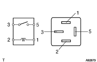
Measure the resistance according to the value(s) in the table below.
Standard Resistance Tester Connection Condition Specified Condition 3 - 5 Battery voltage not applied to terminals 1 and 2 10 kΩ or higher Battery voltage applied to terminals 1 and 2 Below 1 Ω If the result is not as specified, replace the relay.
-
-
INSPECT GLOW PLUG RELAY (GLOW)
-
Measure the resistance according to the value(s) in the table below.
Standard Resistance Tester Connection Condition Specified Condition 3 - 5 Battery voltage not applied to terminals 1 and 2 10 kΩ or higher Battery voltage applied to terminals 1 and 2 Below 1 Ω If the result is not as specified, replace the relay.
-
-
INSPECT NO. 1 INTEGRATION RELAY
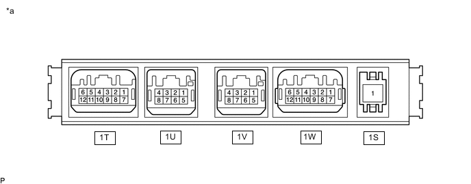
*a Component without harness connected
(No. 1 Integration Relay)
- - Note
-
The EDU relay, IG2 relay, EFI MAIN NO. 1 relay and FUEL PMP relay are built into the No. 1 integration relay.
-
Before performing the relay inspections for the relays of the No. 1 integration relay, inspect the IG2, EFI MAIN NO. 1 and FUEL PMP fuses.
-
Inspect the FUEL PMP relay.
-
Measure the resistance according to the value(s) in the table below.
Standard Resistance Tester Connection Condition Specified Condition 1S-1 - 1V-6 Battery voltage not applied to terminals 1S-1 and 1V-7 10 kΩ or higher Battery voltage applied to terminals 1S-1 and 1V-7 Below 1 Ω If the result is not as specified, replace the No. 1 integration relay.
-
-
Inspect the IG2 relay.
-
Measure the resistance according to the value(s) in the table below.
Standard Resistance Tester Connection Condition Specified Condition 1S-1 - 1V-1 Battery voltage not applied to terminals 1V-2 and 1W-4 10 kΩ or higher Battery voltage applied to terminals 1V-2 and 1W-4 Below 1 Ω If the result is not as specified, replace the No. 1 integration relay.
-
-
Inspect the EFI MAIN NO. 1 relay.
-
Measure the resistance according to the value(s) in the table below.
Standard Resistance Tester Connection Condition Specified Condition 1S-1 - 1W-11 Battery voltage not applied to terminals 1W-8 and 1W-4 10 kΩ or higher Battery voltage applied to terminals 1W-8 and 1W-4 Below 1 Ω If the result is not as specified, replace the No. 1 integration relay.
-
-
Inspect the EDU relay.
-
Measure the resistance according to the value(s) in the table below.
Standard Resistance Tester Connection Condition Specified Condition 1S-1 - 1U-2 Battery voltage not applied to terminals 1S-1 and 1U-1 10 kΩ or higher Battery voltage applied to terminals 1S-1 and 1U-1 Below 1 Ω If the result is not as specified, replace the No. 1 integration relay.
-
-
-
INSPECT MAIN BODY ECU (DRIVER SIDE JUNCTION BLOCK)
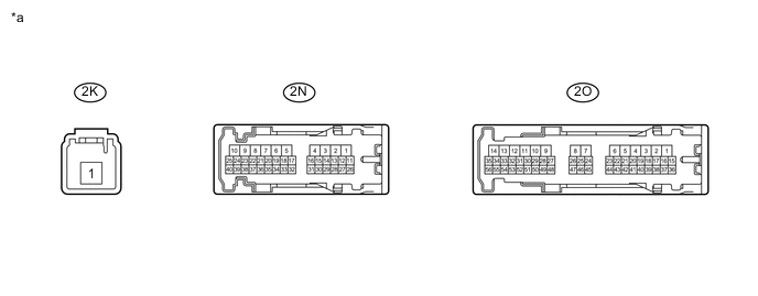
*a Component without harness connected
(Main Body ECU)
- - Note
-
The ACC relay are built into the main body ECU (driver side junction block).
-
Before performing the relay inspections for the relay of the main body ECU (driver side junction block), inspect the ACC fuse.
-
Inspect the ACC relay.
-
Measure the resistance according to the value(s) in the table below.
Standard Resistance Tester Connection Condition Specified Condition 2K-1 - 2O-50 Battery voltage not applied to terminals 2N-1 and 2O-23 10 kΩ or higher Battery voltage applied to terminals 2N-1 and 2O-23 Below 1 Ω If the result is not as specified, replace the main body ECU.
-
-