ECD SYSTEM, Diagnostic DTC:P0724
| DTC Code | DTC Name |
|---|---|
| P0724 | Brake Switch "B" Circuit High |
DESCRIPTION
This DTC indicates that the stop light switch remains on. When the stop light switch remains on during GO and STOP driving, the ECM interprets this as a fault in the stop light switch. Then the MIL illuminates and the ECM stores the DTC.
| DTC Detection Drive Pattern | DTC Detection Condition | Trouble Area |
|---|---|---|
| Accelerate the vehicle to 30 km/h (19 mph) or more, depress the brake pedal and decelerate the vehicle to 3 km/h (1.8 mph) or less 5 times. | Stop light switch remains on even when vehicle is driven in GO (30 km/h (19 mph) or more) and STOP (less than 3 km/h (1.8 mph)) pattern 5 times (2 trip detection logic). |
|
| DTC No. | Data List |
|---|---|
| P0724 | Stop Light Switch |
WIRING DIAGRAM
Refer to DTC P0504 Click here.
CAUTION / NOTICE / HINT
Note
After replacing the ECM, the new ECM needs registration (See page ) and initialization Click here.
Tech Tips
Read freeze frame data using the intelligent tester. Freeze frame data records the engine condition when malfunctions are detected. When troubleshooting, freeze frame data can help determine if the vehicle was moving or stationary, if the engine was warmed up or not, and other data from the time the malfunction occurred.
PROCEDURE
-
READ VALUE USING INTELLIGENT TESTER (STOP LIGHT SWITCH)
-
Connect the intelligent tester to the DLC3.
-
Turn the ignition switch to ON.
-
Enter the following menus: Powertrain / Engine and ECT / Data List / Stop Light Switch.
-
Read the value displayed on the tester when the brake pedal is depressed and released.
OK Brake Pedal Display Released OFF Depressed ON
OK 
CONFIRM WHETHER MALFUNCTION HAS BEEN SUCCESSFULLY REPAIRED Click here
NG 
-
-
CHECK STOP LIGHT SWITCH ASSEMBLY (INSTALLATION)
-
Check the stop light switch assembly installation Click here.
NG
SECURELY REINSTALL STOP LAMP SWITCH ASSEMBLY Click here
OK
-
-
CHECK ECM (STP VOLTAGE)
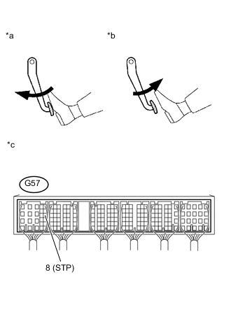
Text in Illustration *a Brake pedal depressed *b Brake pedal released *c Component with harness connected
(ECM)
-
Disconnect the ECM connector.
-
Turn the ignition switch to ON.
-
Measure the voltage according to the value(s) in the table below.
Standard Voltage Tester Connection Brake Pedal Condition Specified Condition G57-8 (STP) - Body ground Released 0 to 3 V Depressed 11 to 14 V -
Reconnect the ECM connector.
OK
REPLACE ECM Click here
NG
-
-
CHECK STOP LAMP SWITCH ASSEMBLY (TERMINAL B VOLTAGE)
-
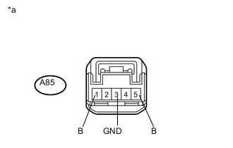
Text in Illustration *a Front view of wire harness connector
(to Stop Light Switch)
Disconnect the stop light switch connector.
-
Measure the voltage according to the value(s) in the table below.
Standard Voltage Tester Connection Condition Specified Condition A85-1 (B) - Body ground Always 11 to 14 V A85-5 (B) - Body ground Ignition switch ON 11 to 14 V -
Measure the resistance according to the value(s) in the table below.
Standard Resistance Tester Connection Condition Specified Condition A85-3 (GND) - Body ground Always Below 1 Ω -
Reconnect the stop light switch assembly connector.
NG
REPAIR OR REPLACE HARNESS OR CONNECTOR Click here
OK
-
-
CHECK HARNESS AND CONNECTOR (STOP LIGHT SWITCH ASSEMBLY - ECM)
-
Disconnect the stop light switch assembly connector.
-
Disconnect the ECM connector.
-
Measure the resistance according to the value(s) in the table below.
Standard Resistance (Check for Open) Tester Connection Condition Specified Condition A85-2 (L) - G57-8 (STP) Always Below 1 Ω A85-4 (L) - G57-9 (ST1-) Always Below 1 Ω Standard Resistance (Check for Short) Tester Connection Condition Specified Condition A85-2 (L) or G57-8 (STP) - Body ground Always 10 kΩ or higher A85-4 (L) or G57-9 (ST1-) - Body ground Always 10 kΩ or higher -
Reconnect the stop light switch assembly connector.
-
Reconnect the ECM connector.
NG
REPAIR OR REPLACE HARNESS OR CONNECTOR Click here
OK
-
-
REPLACE STOP LIGHT SWITCH ASSEMBLY
-
Replace the stop light switch assembly Click here.
NEXT
CONFIRM WHETHER MALFUNCTION HAS BEEN SUCCESSFULLY REPAIRED Click here
-
-
REPLACE ECM
-
Replace the ECM Click here.
NEXT
CONFIRM WHETHER MALFUNCTION HAS BEEN SUCCESSFULLY REPAIRED Click here
-
-
SECURELY REINSTALL STOP LAMP SWITCH ASSEMBLY
-
Securely reinstall the stop light switch assembly Click here.
NEXT
CONFIRM WHETHER MALFUNCTION HAS BEEN SUCCESSFULLY REPAIRED Click here
-
-
REPAIR OR REPLACE HARNESS OR CONNECTOR
-
Repair or replace the harness or connector.
NEXT
-
-
CONFIRM WHETHER MALFUNCTION HAS BEEN SUCCESSFULLY REPAIRED
-
Connect the intelligent tester to the DLC3.
-
Clear the DTCs Click here.
-
Turn the ignition switch off for 30 seconds or more.
-
Turn the ignition switch to ON and turn the tester on.
-
Start the engine.
-
Accelerate the vehicle to 30 km/h (19 mph) or more, depress the brake pedal and decelerate the vehicle to 3 km/h (1.8 mph) or less 5 times or more.
-
Confirm that the DTC is not output again.
Tech Tips
Perform the following procedure using the tester to determine whether or not the DTC judgment has been carried out.
-
Enter the following menus: Powertrain / Engine and ECT / Utility / All Readiness.
-
Input DTC P0724.
-
Check that STATUS is NORMAL.
Tech Tips
-
If STATUS is NORMAL, DTC judgment is complete and it can be determined that the system is normal.
-
If STATUS is INCOMPLETE or N/A, DTC judgment is incomplete. Perform the following procedure again 5 times: accelerate the vehicle to 30 km/h (19 mph) or more, depress the brake pedal and decelerate the vehicle to 3 km/h (1.8 mph) or less.
-
-
NEXT 
END
-