ECD SYSTEM DATA LIST / ACTIVE TEST
-
DATA LIST
Tech Tips
Using the intelligent tester to read the Data List allows the values or states of switches, sensors, actuators and other items to be read without removing any parts. This non-intrusive inspection can be very useful because intermittent conditions or signals may be discovered before parts or wiring is disturbed. Reading the Data List information early in troubleshooting is one way to save diagnostic time.
Note
In the table below, the values listed under "Normal Condition" are reference values. Do not depend solely on these reference values when deciding whether a part is faulty or not.
-
Warm up the engine.
-
Turn the ignition switch off.
-
Connect the intelligent tester to the DLC3.
-
Turn the ignition switch to ON.
-
Start the engine.
-
Turn the intelligent tester on.
-
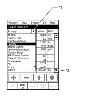
Example *1 Pull Down Menu *2 Measurement Group Enter the following menus: Powertrain / Engine and ECT / Data List.
Tech Tips
-
To display the list box, press the pull down menu button next to "Primary". Then select a measurement group.
-
When you select a measurement group, the ECU data belonging to that group is displayed.
-
Measurement Group List / Description
-
All Data / All data
-
Primary / -
-
Engine Control / Engine control system related data
-
Vehicle Information / Vehicle information
-
Monitor Status / Monitor status related data
-
AF Control System / Not Applicable
-
Catalytic Converter / Not Applicable
-
Evaporative / Not Applicable
-
A/T / Automatic transaxle system related data
-
ETCS / Not Applicable
-
Misfire / Not Applicable
-
Compression / Data used during "Check the Cylinder Compression" Active Test
-
HC Adsorber System / Not Applicable
-
Diesel Driving / Driving condition data
-
Diesel Injection / Fuel system related data
-
Diesel EGR / EGR system related data
-
Diesel Throttle / Diesel throttle system related data
-
Diesel VN Turbo / VN turbo related data
-
Diesel Exhaust / Exhaust system related data
-
Diesel Starting / "Difficult to start" related data
-
Diesel Rough / "Rough idle" related data
-
Diesel Power / "Lack of power" related data
-
-
Check the values by referring to the table below.
Tech Tips
"Result of real-vehicle check" is the assessment of one vehicle. Use it only for reference.
-
-
Engine Control
Vehicle Speed Tester Display Measurement Item/Range Normal Condition Type Cause of Out of Range Vehicle Speed Vehicle speed/
Min.: 0 km/h, Max.: 255 km/h
Actual vehicle speed Sensor output (speed sensor)
-
Speed sensor
-
Speed sensor circuit
Symptoms when out of range:
-
Diagnostic Note:
-
Target Idle Engine Speed Tester Display Measurement Item/Range Normal Condition Type Cause of Out of Range Target Idle Engine Speed Target Idling Engine Speed/
Min.: 0 rpm, Max.: 10000 rpm
-
660 rpm*1
-
700 rpm (shift lever in P or N)*2
-
660 rpm (shift lever in D)*2
- - Symptoms when out of range:
-
Diagnostic Note:
-
-
*1: for Manual Transaxle
-
*2: for Automatic Transaxle
Engine Speed Tester Display Measurement Item/Range Normal Condition Type Cause of Out of Range Engine Speed Engine speed/
Min.: 0 rpm, Max.: 6000 rpm
-
50 to 400 rpm: Cranking
-
610 to 710 rpm: Idling with warm engine*1
-
650 to 750 rpm: Idling with warm engine*2
Sensor output (crankshaft position sensor)
-
Crankshaft position sensor
-
Crankshaft position sensor circuit
Symptoms when out of range:
-
Diagnostic Note:
When the crankshaft position sensor is malfunctioning, "Engine Speed" is approximately 0 or varies greatly from the actual engine speed.
-
*1: for Manual Transaxle
-
*2: for Automatic Transaxle
Calculate Load Tester Display Measurement Item/Range Normal Condition Type Cause of Out of Range Calculate Load Load calculated by ECM/
Min.: 0%, Max.: 100%
-
Idling: 7 to 26%
-
Running without load (2500 rpm): 10 to 20%
Calculated by ECM Malfunction in which turbo pressure or Mass Air Flow decreases Diagnostic Note:
Calculated load = (Final injection volume / max. injection volume at current engine speed) x 100.
MAF Tester Display Measurement Item/Range Normal Condition Type Cause of Out of Range MAF Air flow rate from mass air flow meter/
Min.: 0 g/sec., Max.: 400 g/sec.
-
Idling: 5 to 12 g/sec.
-
Running without load (2000 rpm): 15 to 35 g/sec.
Tech Tips
Depends on EGR rate
Sensor output (mass air flow meter)
-
Mass air flow meter
-
Mass air flow meter circuit
-
Intake related clog or leak
-
Exhaust related clog
-
Turbocharger sub-assembly
-
Leak or clog in passages for turbocharger
-
Malfunction in which EGR valve does not close
Symptoms when out of range:
Rough idling
Diagnostic Note:
-
Based on the MAF, the ECM controls the fuel injection volume, injection timing, EGR, etc.
-
If the value is always approximately 0 g/sec.:
-
Mass air flow meter power source circuit is open.
-
VG circuit is open or shorted.
-
EVG circuit is open.
Atmosphere Pressure Tester Display Measurement Item/Range Normal Condition Type Cause of Out of Range Atmosphere Pressure Atmospheric pressure value/
Min.: 50 kPa, Max.: 120 kPa
Actual atmospheric pressure Sensor output (atmospheric pressure sensor (built into ECM)) Atmospheric pressure sensor itself has failed (atmospheric pressure sensor is inside the ECM) Symptoms when out of range:
-
Diagnostic Note:
-
With the ignition switch ON, when the difference between the atmospheric pressure sensor and intake manifold absolute pressure is 10 kPa or more, there is a malfunction in one of the sensors.
-
With the ignition switch ON, when the atmospheric pressure is 0 kPa or 140 kPa, there is a malfunction in the sensor circuit.
-
Standard atmospheric pressure: 101 kPa.
-
For every 100 m increase in elevation, pressure drops by 1 kPa.
This varies by weather (high atmospheric pressure, low atmospheric pressure).
MAP Tester Display Measurement Item/Range Normal Condition Type Cause of Out of Range MAP Absolute pressure inside intake manifold/
Min.: 0 kPa, Max.: 255 kPa
-
Idling: 94 to 104 kPa (depending on barometric pressure)
-
Engine running at 3000 rpm: 100 to 150 kPa
Sensor output (manifold absolute pressure sensor)
-
Manifold absolute pressure sensor
-
Intake related clog or leak
-
Exhaust related clog
-
Turbocharger sub-assembly
-
Leak or clog in passages for turbocharger
-
EGR valve stuck open
-
Exhaust leak
-
Throttle valve stuck closed
Symptoms when out of range:
Lack of power
Diagnostic Note:
-
When the ignition switch is ON or the vehicle is idling, the intake manifold absolute pressure and atmospheric pressure are approximately the same (standard atmospheric pressure = 101 kPa).
Above approximately 1500 rpm, the turbo becomes effective and the pressure becomes higher than atmospheric pressure.
-
Inspect while comparing with "Target Booster Pressure".
-
With the accelerator fully open, if the actual manifold absolute pressure (MAP) is low compared to the target booster pressure by at least 20 kPa for 5 seconds or more, a feeling of insufficient power will occur.
Coolant Temp Tester Display Measurement Item/Range Normal Condition Type Cause of Out of Range Coolant Temp Engine coolant temperature/
Min.: -40°C, Max.: 140°C
After warming up engine: 70 to 90°C (158 to 194°F) Sensor output (engine coolant temperature sensor)
-
Engine coolant temperature sensor
-
Thermostat
Symptoms when out of range:
Difficulty starting when engine is cold, rough idle, black smoke, lack of power
Diagnostic Note:
-
If the value is -40°C (-40°F) or 140°C (284°F), the sensor circuit is open or shorted.
-
After a long soak, the coolant temperature, intake air temperature and ambient temperature are approximately equal.
Intake Air Tester Display Measurement Item/Range Normal Condition Type Cause of Out of Range Intake Air Intake air temperature/
Min.: -40°C, Max.: 140°C
Equivalent to temperature at location of mass air flow meter Sensor output (intake air temperature sensor (built into mass air flow meter)) Intake air temperature sensor Symptoms when out of range:
-
Diagnostic Note:
-
After a long soak, the engine coolant temperature, intake air temperature and ambient temperature are approximately equal.
-
If the value is -40°C (-40°F) or 140°C (284°F), the sensor circuit is open or shorted.
Intake Air Temp (Turbo) Supported Tester Display Measurement Item/Range Normal Condition Type Cause of Out of Range Intake air temp (Turbo) support Unsupp or Supp - - - Diagnostic Note:
-
Supp: The item is supported by the vehicle.
-
Unsupp: The monitor is not supported by the vehicle.
Intake Air Temp (Turbo) Tester Display Measurement Item/Range Normal Condition Type Cause of Out of Range Intake Air Temp (Turbo) Intake air temperature after intercooler/
Min.: -40°C, Max.: 190°C
70°C (158°F) or less Sensor output (intake air temperature sensor after intercooler) Decreased cooling efficiency of intercooler (contamination, clogging) Diagnostic Note:
-
This is the intake air temperature at the intake manifold (after the intercooler).
-
During fail-safe operation, the value is set to 165°C (329°F). As the value is set to a high temperature, the turbo pressure may be suppressed and there may be a lack of power.
Ambient Temperature Tester Display Measurement Item/Range Normal Condition Type Cause of Out of Range Ambient tempereture Min.: -40°C, Max.: 140°C Equivalent to ambient air temperature - - Diagnostic Note:
-
Engine Run Time Tester Display Measurement Item/Range Normal Condition Type Cause of Out of Range Engine Run Time Engine run time/
Min.: 0 sec., Max.: 65535 sec.
Time after the ignition switch turned to ON Result of ECU calculations (using the engine speed) - Diagnostic Note:
Time passed since the ignition switch was turned to ON.
Initial Engine Coolant Temp Tester Display Measurement Item/Range Normal Condition Type Cause of Out of Range Initial Engine Coolant Temp Initial engine coolant temperature/
Min.: -40°C, Max.: 120°C
Engine coolant temperature when engine started Sensor output when engine started - Diagnostic Note:
For freeze frame data, this tells whether the malfunction happened at a cold start or with a warm engine.
Battery Voltage Tester Display Measurement Item/Range Normal Condition Type Cause of Out of Range Battery Voltage Battery voltage/
Min.: 0 V, Max.: 15 V
11 to 14 V - - Symptoms when out of range:
If 5 V or less, starting becomes difficult
Diagnostic Note:
If 11 V or less, characteristics of some electrical components change.
Alternate Duty Ratio Tester Display Measurement Item/Range Normal Condition Type Cause of Out of Range Alternate Duty Ratio Alternator generation duty ratio/
Min.: 0%, Max.: 100%
-
No electrical load at idling:
20 to 60%
-
High electrical load at idling:
100%
Duty value from ALT terminal
-
Battery deterioration
-
Alternator malfunction
-
Electric load, lights, etc.
Diagnostic Note:
-
This is outputs the alternator generation duty and is used to determine the electrical load.
-
Can be used to determine whether a higher-than-normal injection volume at idle, etc. is due to electrical loading or from some other source. For example, when the duty is not high but the idling injection volume is high, there is injector volume degradation or high engine friction.
-
Can be used for judging whether or not a malfunctioning component in the electrical system is generating continual generation requests (e.g., battery deterioration is causing an unending full recharge request, etc.). Regardless of whether or not an auxiliary device like the A/C or heater is active, if the alternator duty is always at the maximum value, there is an electrical system abnormality, like battery deterioration.
Glow Relay Request Tester Display Measurement Item/Range Normal Condition Type Cause of Out of Range Status of the glow relay request ON or OFF - - - Diagnostic Note:
-
Glow indicator support Tester Display Measurement Item/Range Normal Condition Type Cause of Out of Range Glow indicator support Unsupp or Supp - - - Diagnostic Note:
-
Supp: The item is supported by the vehicle.
-
Unsupp: The monitor is not supported by the vehicle.
Glow Indicator Tester Display Measurement Item/Range Normal Condition Type Cause of Out of Range Status of the glow indicator ON or OFF - - - Diagnostic Note:
-
Accel Position Tester Display Measurement Item/Range Normal Condition Type Cause of Out of Range Accel Position Accelerator position status/
Min.: 0%, Max.: 100%
-
Accelerator pedal released:
0%
-
Accelerator pedal fully depressed:
100%
-
Accelerator pedal position sensor opening position
-
ECT requested opening position
-
Cruise requested opening position
-
VSC requested opening position
- Diagnostic Note:
-
"Accel Position" is the accelerator opening amount (%) for engine control use.
-
When the accelerator pedal position sensor output itself (Accelerator Position 1, Accelerator Position 2) is in the normal voltage range, another actuator malfunction has caused the fail-safe function to restrict the accelerator.
-
Without cruise, ECT or VSC requests, and without accelerator restriction by the fail-safe function, this is adjusted in proportion to the amount the accelerator pedal is depressed by the driver.
-
Accelerator pedal released: 0%
-
Accelerator pedal fully depressed: 100%
Tech Tips
Accel Sens. No.1 Volt % and Accel Sens. No.2 Volt % express the value obtained by dividing the output voltage from the accelerator pedal position sensor by 5. This is used only for diagnosing malfunctions in the accelerator pedal position sensor. Under normal conditions, it is sufficient to only check the final accelerator opening angle value "Accel Position".
Accel Sens. No.1 Volt % Tester Display Measurement Item/Range Normal Condition Type Cause of Out of Range Accel Sens. No.1 Volt % Accelerator position No. 1/
Min.: 0%, Max.: 100%
-
Accelerator pedal released:
8 to 28%
-
Accelerator pedal fully depressed:
51 to 86%
Sensor output (Accelerator pedal position sensor) - Diagnostic Note:
Read value with ignition switch ON (do not start engine)
Accel Sens. No.2 Volt % Tester Display Measurement Item/Range Normal Condition Type Cause of Out of Range Accel Sens. No.2 Volt % Accelerator position No. 2/
Min.: 0%, Max.: 100%
-
Accelerator pedal released:
30 to 55%
-
Accelerator pedal fully depressed:
73 to 98%
Sensor output (Accelerator pedal position sensor) - Diagnostic Note:
Read value with ignition switch ON (do not start engine)
Starter Signal Tester Display Measurement Item/Range Normal Condition Type Cause of Out of Range Starter Signal Starter signal/
ON or OFF
ON: Cranking -
-
OFF malfunction (ignition switch (STA) is ON but the signal is OFF and the starter is operating): Wire harness is open or shorted to ground
-
ON malfunction (ignition switch (STA) is off but the signal is ON and the starter is not operating): Wire harness is shorted to +B
-
Operation malfunction: ignition switch malfunction, starter relay malfunction, starter malfunction, battery or battery cable is defective, or wire harness is open or shorted
Symptoms when out of range:
-
Ignition switch is ON but the starter does not operate: Starting is not possible
-
Ignition switch is off but the starter continues to operate: STA signal malfunction (P0617) is stored
Diagnostic Note:
Ignition switch (STA) output:
-
ON: Starter is operating.
-
OFF: Starter is not operating.
Power Steering Signal Tester Display Measurement Item/Range Normal Condition Type Cause of Out of Range Power Steering Signal Power steering switch status/
ON or OFF
ON: Power steering operation Switch output (power steering switch)
-
OFF malfunction: Wire harness (power steering switch to ECM) is open or shorted to ground
-
ON malfunction: Wire harness (power steering switch to ECM) is shorted to +B
-
Power steering switch malfunction
Symptoms when out of range:
-
OFF malfunction (OFF during power steering operation): Engine speed decreases temporarily when power steering is operating
Diagnostic Note:
-
A/C Signal Tester Display Measurement Item/Range Normal Condition Type Cause of Out of Range A/C Signal A/C (Air Conditioner) signal/
ON or OFF
ON: A/C on A/C operation signal output from A/C amplifier
-
ON: Operating
-
OFF: Not operating
-
A/C switch
-
A/C amplifier
-
A/C system malfunction, wire harness between A/C amplifier and ECU open or shorted
Symptoms when out of range:
OFF malfunction (OFF even when A/C switch is turned on):
-
Engine speed decreases temporarily when the A/C is operating.
Diagnostic Note:
-
Stop Light Switch Tester Display Measurement Item/Range Normal Condition Type Cause of Out of Range Stop Light Switch Stop light switch/
ON or OFF
-
ON: Brake pedal depressed
-
OFF: Brake pedal released
Switch output (stop light switch)
-
OFF malfunction: Wire harness (stop light switch to ECM, stop light switch to +B) open or shorted to ground
-
ON malfunction: Wire harness (stop light switch to ECM) shorted to +B
-
Stop light switch
Symptoms when out of range:
Stop light switch malfunction DTC P0504 is stored
Diagnostic Note:
Stop light switch (STP) operation condition:
-
ON: Light is on (Brake pedal is depressed).
-
OFF: Light is off (Brake pedal is released).
Intank Fuel Pump Tester Display Measurement Item/Range Normal Condition Type Cause of Out of Range Intank Fuel Pump In-tank fuel pump status/
ON or OFF
Operates according to fuel consumption amount
(Operates after about 10 minutes of driving)
Operation command - Symptoms when out of range:
-
Diagnostic Note:
In-tank fuel pump operation condition:
-
ON: In-tank fuel pump is operating.
-
Only for vehicles equipped with a double tank.
Immobiliser Communication Tester Display Measurement Item/Range Normal Condition Type Cause of Out of Range Immobiliser Communication Immobiliser communication/
ON or OFF
-
ON: Normal
-
OFF: Engine cannot be started due to immobiliser communication malfunction
-
-
Use of a non-registered key
-
Key battery is fully depleted
Symptoms when out of range:
-
Diagnostic Note:
-
Neutral Position SW Signal Tester Display Measurement Item/Range Normal Condition Type Cause of Out of Range Neutral Position SW Signal Neutral position switch status/
ON or OFF
ON: Shift lever in neutral Switch output (neutral position switch) - Symptoms when out of range:
-
Diagnostic Note:
-
Clutch Switch Tester Display Measurement Item/Range Normal Condition Type Cause of Out of Range Clutch Switch Clutch switch/
ON or OFF
ON: Clutch pedal depressed Switch output (clutch switch) - Symptoms when out of range:
When OFF with the clutch pedal depressed, the engine does not start.
Diagnostic Note:
-
ACT VSV Tester Display Measurement Item/Range Normal Condition Type Cause of Out of Range ACT VSV A/C cut status for Active Test/
ON or OFF
- - - Diagnostic Note:
"Control the A/C Cut Signal" Active Test support data.
ACM Inhibit Tester Display Measurement Item/Range Normal Condition Type Cause of Out of Range ACM Inhibit VSV for engine mount status/
ON or OFF
- - - Diagnostic Note:
-
VSV for engine mount status:
-
Ignition switch is ON: OFF.
-
Idling: ON.
-
"Control the ACM Inhibit" Active Test support data.
TC and TE1 Tester Display Measurement Item/Range Normal Condition Type Cause of Out of Range TC and TE1 TC and TE1 connection status for Active Test/
ON or OFF
- - - Diagnostic Note:
When the "Connect the TC and TE1" Active Test is performed, the system behaves as if TC and CG were connected.
Check Mode Tester Display Measurement Item/Range Normal Condition Type Cause of Out of Range Check Mode Check mode/
ON or OFF
ON: Check mode on - - Diagnostic Note:
Check Mode: The mode in which certain DTCs can be detected more easily and with higher sensitivity.
SPD Test Result Tester Display Measurement Item/Range Normal Condition Type Cause of Out of Range SPD Test Result Check mode result for vehicle speed sensor/
Compl or Incompl
- - - Diagnostic Note:
SPD Test Result: Check mode result for the vehicle speed sensor.
MIL Tester Display Measurement Item/Range Normal Condition Type Cause of Out of Range MIL MIL status/
ON or OFF
OFF: MIL off - - MIL ON Run Distance Tester Display Measurement Item/Range Normal Condition Type Cause of Out of Range MIL ON Run Distance Distance traveled with MIL on/
Min.: 0 km, Max.: 65535 km
Distance traveled after DTC stored Result of ECU calculations (using the vehicle speed) - Diagnostic Note:
-
Distance traveled after a DTC is stored.
-
Cleared when the cable is disconnected from the negative (-) battery terminal, or when the DTC is cleared using the intelligent tester.
Running Time from MIL ON Tester Display Measurement Item/Range Normal Condition Type Cause of Out of Range Running Time from MIL ON Running time after MIL turns on/
Min.: 0 min., Max.: 65535 min.
Running time after MIL turns on - - Diagnostic Note:
-
Engine run time since the MIL illumination.
-
Cleared when the cable is disconnected from the negative (-) battery terminal, or when the DTC is cleared using the intelligent tester.
Time after DTC Cleared Tester Display Measurement Item/Range Normal Condition Type Cause of Out of Range Time after DTC Cleared Time after DTC cleared/
Min.: 0 min., Max.: 65535 min.
Time after DTCs cleared - - Diagnostic Note:
Time elapsed since the DTCs were cleared (or shipment from the factory).
Distance from DTC Cleared Tester Display Measurement Item/Range Normal Condition Type Cause of Out of Range Distance from DTC Cleared Distance driven after DTC cleared/
Min.: 0 km, Max.: 65535 km
Distance driven after DTCs cleared - - Diagnostic Note:
-
Distance driven since the DTCs were cleared.
-
(Data List "Distance from DTC clear") - (Freeze frame data "Distance from DTC cleared") = Distance driven since the abnormality occurred.
Warmup Cycle Cleared DTC Tester Display Measurement Item/Range Normal Condition Type Cause of Out of Range Warmup Cycle Cleared DTC Warmup cycles after DTC cleared/
Min.: 0, Max.: 255
- - - Diagnostic Note:
-
Number of engine warmup since DTCs were cleared.
-
(Data List "Warmup Cycle Cleared DTC") - (Freeze frame data "Warmup Cycle Cleared DTC") = Warmup cycles since the abnormality occurred.
OBD Requirements Tester Display Measurement Item/Range Normal Condition Type Cause of Out of Range OBD Requirements Identifying OBD requirement - - - Diagnostic Note:
Euro-OBD
Number of Emission DTC Tester Display Measurement Item/Range Normal Condition Type Cause of Out of Range Number of Emission DTC Number of emissions-related DTCs - - Diagnostic Note:
-
Complete Parts Monitor Tester Display Measurement Item/Range Normal Condition Type Cause of Out of Range Complete Parts Monitor Complete parts monitor/
Not Avl or Avail
- - - Diagnostic Note:
-
Swirl Control Valve VSV Tester Display Measurement Item/Range Normal Condition Type Cause of Out of Range Swirl Control Valve VSV Status of VSV for swirl control valve/
ON or OFF
ON: Idling - - Diagnostic Note:
-
Intake Air Temp (Turbo) Tester Display Measurement Item/Range Normal Condition Type Cause of Out of Range Intake Air Temp (Turbo) Intake air temperature after intercooler/
Min.: -40°C, Max.: 190°C
70°C (158°F) or less Sensor output (intake air temperature sensor after intercooler) Decreased cooling efficiency of intercooler (contamination, clogging) Diagnostic Note:
-
This is the intake air temperature at the intake manifold (after the intercooler).
-
During fail-safe operation, the value is set to 165°C (329°F). As the value is set to a high temperature, the turbo pressure may be suppressed and there may be a lack of power.
-
-
Compression
Engine Speed of Cyl #1 Tester Display Measurement Item/Range Normal Condition Type Cause of Out of Range Engine Speed of Cyl #1 Engine speed for No. 1 cylinder/
Min.: 0 rpm, Max.: 6000 rpm
Engine speeds of all cylinders almost same - Cyl #1 compression goes down Symptoms when out of range:
When the engine speeds of all cylinders are not equal, idling will be rough.
Diagnostic Note:
-
Output only when the "Check the Cylinder Compression" Active Test is performed.
-
Indicates the speed of each cylinder when cranking.
Example - Normal: Engine speeds of all cylinders are approximately equal.
When No. 1 cylinder compression is low, "Engine Speed of Cyl #1" is approximately 300 rpm, and "Engine Speed of Cyl #2 to #4" is approximately 200 rpm.
Engine Speed of Cyl #2 Tester Display Measurement Item/Range Normal Condition Type Cause of Out of Range Engine Speed of Cyl #2 Engine speed for No. 2 cylinder/
Min.: 0 rpm, Max.: 6000 rpm
- - - Engine Speed of Cyl #3 Tester Display Measurement Item/Range Normal Condition Type Cause of Out of Range Engine Speed of Cyl #3 Engine speed for No. 3 cylinder/
Min.: 0 rpm, Max.: 6000 rpm
- - - Engine Speed of Cyl #4 Tester Display Measurement Item/Range Normal Condition Type Cause of Out of Range Engine Speed of Cyl #4 Engine speed for No. 4 cylinder/
Min.: 0 rpm, Max.: 6000 rpm
- - - Av Engine Speed of All Cyl Tester Display Measurement Item/Range Normal Condition Type Cause of Out of Range Average enginespeed for allcylinders Min.: 0 rpm, Max.: 51199rpm Engine speeds of all cylinders almost same - Cyl #1 compression goes down Symptoms when out of range:
When the engine speeds of all cylinders are not equal, idling will be rough.
Diagnostic Note:
-
Output only when the Active Test "Check the Cylinder Compression" is performed.
-
Indicates the average engine speed of all cylinders during cranking.
-
-
Vehicle Information
Model Code Tester Display Measurement Item/Range Normal Condition Type Cause of Out of Range Model Code Model code - - - Diagnostic Note:
Identifying model code:
Engine Type Tester Display Measurement Item/Range Normal Condition Type Cause of Out of Range Engine Type Engine type - - - Diagnostic Note:
Identifying engine type: 1KDFTV
Cylinder Number Tester Display Measurement Item/Range Normal Condition Type Cause of Out of Range Cylinder Number Cylinder number/
Min.: 0, Max.: 255
- - - Diagnostic Note:
Identifying cylinder number: 4
Transmission Type Tester Display Measurement Item/Range Normal Condition Type Cause of Out of Range Transmission Type Transaxle type/
MT or ECT 5th
- - - Diagnostic Note:
Identifying transaxle type:
-
MT: Manual transaxle
-
ECT 5th: Automatic transaxle
Destination Tester Display Measurement Item/Range Normal Condition Type Cause of Out of Range Destination Destination - - - Diagnostic Note:
Identifying destination:
Model Year Tester Display Measurement Item/Range Normal Condition Type Cause of Out of Range Model Year Model year/
Min.: 1900, Max.: 2155
- - - Diagnostic Note:
Identifying model year: 20##
System Identification Tester Display Measurement Item/Range Normal Condition Type Cause of Out of Range System Identification System identification - - - Diagnostic Note:
Identifying engine type: Diesel
VN Turbo Type Tester Display Measurement Item/Range Normal Condition Type Cause of Out of Range VN Turbo Type VN turbo type/
Not, Commo or Vacuum
Commo - - Symptoms when out of range:
-
Diagnostic Note:
Indicates the VN turbo vane actuation method.
-
DC motor system.
-
Negative-pressure diaphragm system.
-
Step motor system.
-
-
Diesel Injection
Target Common Rail Pressure Tester Display Measurement Item/Range Normal Condition Type Cause of Out of Range Target Common Rail Pressure Target common rail pressure/
Min.: 0 kPa, Max.: 250000 kPa
30000 to 160000 kPa when engine running Target common rail pressure (ECU calculated value) - Symptoms when out of range:
-
Diagnostic Note:
-
Inspect the (actual) fuel pressure, comparing it with the common rail target value.
-
Considered normal when the actual fuel pressure is within +/-5000 kPa of the target fuel pressure under stable conditions.
Common Rail Pressure Supported Tester Display Measurement Item/Range Normal Condition Type Cause of Out of Range Common rail pressure support Unsupp or Supp - - - Diagnostic Note:
-
Supp: The item is supported by the vehicle.
-
Unsupp: The monitor is notsupported by the vehicle.
Common Rail Pressure Tester Display Measurement Item/Range Normal Condition Type Cause of Out of Range Common Rail Pressure Fuel pressure/
Min.: 0 kPa, Max.: 250000 kPa
Idling: 30000 to 40000 kPa Sensor output (fuel pressure sensor)
-
Fuel supply pump assembly
-
High pressure pipes
-
Fuel pressure sensor
-
Injector assembly
-
Feed pump (fuel supply pump assembly)
-
Fuel filter element sub-assembly
-
Pressure limiter
-
Air in the fuel pipes
-
Lack of fuel
Symptoms when out of range:
Difficult to start, poor driveability, lack of power, abnormal combustion noise
Diagnostic Note:
-
Common rail pressure is the actual common rail fuel pressure.
-
Inspect by comparing the fuel pressure with the target fuel pressure.
-
When in a stable condition such as when idling, the fuel pressure is within +/-5000 kPa of the target fuel pressure.
-
The ECM uses fuel pressure for feedback control of the target fuel pressure via the supply pump.
The injection amount is determined based on the injection timing and fuel pressure.
Also, the spray pattern is selected based on the fuel pressure.
-
For startup, at least 25000 kPa of fuel pressure is needed (take care as there is a response lag when the pressure rises).
-
When the fuel pressure is below 25000 kPa, it may cause rough idling.
-
When the fuel pressure has decreased by 20000 kPa from the target fuel pressure, there may be a lack of power.
-
If the actual fuel pressure is 40000 kPa higher than the target fuel pressure, P1229 will be stored. When it is lower than the target fuel pressure, a lack of power will occur, but a DTC will not be stored.
-
When the fuel pressure is higher than 200000 kPa, DTC P0088 will be stored.
Fuel Temperature Supported Tester Display Measurement Item/Range Normal Condition Type Cause of Out of Range Fuel temperature support Unsupp or Supp - - - Diagnostic Note:
-
Supp: The item is supported by the vehicle.
-
Unsupp: The monitor is not supported by the vehicle.
Target Pump SCV Current Tester Display Measurement Item/Range Normal Condition Type Cause of Out of Range Target Pump SCV Current Final pump current target value/
Min.: 0 mA, Max.: 4000 mA
Idling: 923 to 1123 mA Target value control (pump current)
-
Suction control valve malfunction
-
Clogged fuel filter element sub-assembly
Symptoms when out of range:
Difficulty starting, lack of power or rough idling
Diagnostic Note:
-
ECU-calculated value for the suction control valve actuation target current.
-
Value is large when a high fuel pressure is desired.
-
Normally, the value is between 800 and 2500 mA.
-
If the value is stuck at 3000 mA or higher, it indicates that the operation is poor (poor movement due to deposits, etc.).
-
When this deviates from the standard value, it indicates that for some reason, even though the pump is running hard, the actual fuel pressure is inconsistent with the target fuel pressure.
Pump SCV Learning Value Tester Display Measurement Item/Range Normal Condition Type Cause of Out of Range Pump SCV Learning Value Pump SCV learning value/
Min.: -4096 mA, Max.: 4095.8 mA
Min.: -100 mA
Max.: 100 mA
Learned value
-
Suction control valve malfunction
-
Clogged fuel filter element sub-assembly
Symptoms when out of range:
Difficulty starting, lack of power or rough idling
Diagnostic Note:
If the value is stuck at 200 mA or higher or -200 mA or less, it indicates that the operation is poor (poor movement due to deposits, etc.).
Pump SCV Status Tester Display Measurement Item/Range Normal Condition Type Cause of Out of Range Pump SCV Status ON or OFF - - - Diagnostic Note:
-
Pump SCV Duty Request Tester Display Measurement Item/Range Normal Condition Type Cause of Out of Range Pump SCV duty request Min.: 0%, Max.: 39.9% - - - Diagnostic Note:
-
Inj. FB Vol. for Idle Tester Display Measurement Item/Range Normal Condition Type Cause of Out of Range Inj. FB Vol. for Idle Idle stability status integral control volume/
Min.: -80 mm3/st, Max.: 79 mm3/st
-10 to 10 mm3/st
- - Symptoms when out of range:
Engine friction problem, compression problem or injector breakdown
Diagnostic Note:
-
When the actual engine speed does not match the target idling speed, this corrects the injection volume.
Abnormal if 10 mm3/st or more, or -10 mm3/st or less.
-
Only calculated and reflected at idle.
Injection Volume Tester Display Measurement Item/Range Normal Condition Type Cause of Out of Range Injection Volume Injection volume/
Min.: 0 mm3/st, Max.: 1279.98 mm3/st
Idling: 3.0 to 10 mm3/st
Calculated value - Symptoms when out of range:
-
Diagnostic Note:
-
Injection amount for each combustion.
-
If injector assemblies are clogged fuel quality is poor, the fuel filter element sub-assembly is clogged, or engine friction increases, "Injection Volume" will increase.
-
If there is a malfunction due to low turbocharger pressure or a low intake air volume, the injection volume is limited and there is a lack of power.
Inj Vol Feedback Learning Tester Display Measurement Item/Range Normal Condition Type Cause of Out of Range Inj Vol Feedback Learning Injection volume feedback learning value:
Min.: -10 mm3/st, Max.: 9.92 mm3/st
Idling: -4.0 to 4.0 mm3/st
Learned value
-
Injector assembly
-
Fuel filter element sub-assembly
-
Inferior quality fuel
Symptoms when out of range:
-
Diagnostic Note:
-
"Inj Vol Feedback Learning" is calculated by the deviation of injection volume at idle speed when the engine is warmed up.
-
When the engine is warmed up and in a stable idling condition, this learning will be performed.
-
When poor quality fuel or sustained low-speed driving causes a reduction in injector nozzle hole area (reducing injection volume), the "Inj Vol Feedback Learning" will become an abnormal value (for example, 2.0 mm3/st). At that time, if all of "Injection Feedback Value #1 to #4" are within specifications (for example, less than 2 mm3/st), all cylinders are considered to be malfunctioning. If "Injection Feedback Value #1 to #4" is large at only one cylinder (for example, more than 3 mm3/st), that cylinder may have a malfunction.
-
Other than the injector assemblies, fuel filter element sub-assembly pore blockage, poor-quality fuel, compression loss and large engine friction can all cause "Inj Vol Feedback Learning" to be abnormal.
-
When the engine is started cold, the idling speed is high and gradually slows down in accordance with the increase in engine coolant temperature. If the changing value of the idling speed is unstable while the engine is warming up, check "Inj. FB Vol. For Idle".
-
When combustion noise or driveability is bad, check "Inj Vol Feedback Learning" as part of the injection system deterioration diagnosis.
-
Only when the ignition switch is turned off is the learned value updated gradually.
Pilot Quantity Learning Tester Display Measurement Item/Range Normal Condition Type Cause of Out of Range Pilot Quantity Learning State of "Pilot Quantity Learning"/
Standby / Wait / Learn / Stop / Comple
- Calculated value - Diagnostic Note:
If "Pilot Quantity Learning" is incomplete, the MIL illuminates and DTC P1601 is stored.
Actuator Pilot Quantity Learning Tester Display Measurement Item/Range Normal Condition Type Cause of Out of Range Status of the actuator pilot quantity learning Ready or NG - - - Diagnostic Note:
-
Fuel Return Temp Tester Display Measurement Item/Range Normal Condition Type Cause of Out of Range Fuel Return Temp Fuel return temperature/
Min.: -40°C, Max.: 140°C
Idling after engine warmed-up: 35 to 85°C - - Diagnostic Note:
If the "Fuel Return Temp" value is not between 35°C (95°F) and 110°C (230°F), "Pilot Quantity Learning" is prohibited.
Injection Pressure Correction Tester Display Measurement Item/Range Normal Condition Type Cause of Out of Range Injection Pressure Correction Injection pressure feedback compensation volume/
Min.: -500 mm3/st, Max.: 780 mm3/st
-400 to 400 mm3/st at standard temperature
Calculated value
-
Suction control valve malfunction
-
Clogged fuel filter element sub-assembly
Symptoms when out of range:
-
Diagnostic Note:
-
When the (actual) fuel pressure is equal to the target fuel pressure, this value becomes 0.
-
This indicator can be used for diagnosing supply pump related malfunctions.
-
When this value (absolute value) is large, it indicates that the difference between the actual and target fuel pressure is also large.
A positive value indicates that the pressure feed is being increased due to insufficient pressure. A negative value indicates that pressure is being reduced due to excessive rail pressure.
When the suction control valve does not close properly, it causes rail overpressure, and this value and the "Pump SCV Learning Value" slip to the negative volume side.
Injection EDU Relay Request Tester Display Measurement Item/Range Normal Condition Type Cause of Out of Range Status of the EDU relay request ON or OFF ON: EDU relay ON - - Diagnostic Note:
-
Injection Feedback Val #1 Tester Display Measurement Item/Range Normal Condition Type Cause of Out of Range Injection Feedback Val #1 Injection volume correction for No. 1 cylinder/
Min.: -10 mm3/st, Max.: 10 mm3/st
Idling: -3.0 to 3.0 mm3/st
Learned value
-
Injector clogging
-
Injector deterioration
-
Decrease in cylinder compression
-
Injector compensation code is incorrectly set (forgot to input code after replacement or made mistake during setting of code after replacing ECM with one from another vehicle)
Symptoms when out of range:
Rough idling, black smoke, white smoke, poor driveability, lack of power, abnormal combustion noise, difficult to start
Diagnostic Note:
-
When idling after warmup, the injection amount for each cylinder is corrected to optimize the difference between the engine speed of each cylinder.
Example: For cylinders that are slowing the engine speed compared to other cylinders, the injection volume is increased.
-
"Injection Feedback Val" more than 3.0 mm3/st: Injector breakdown is causing injection volume deviation, or insufficient compression is causing poor combustion.
-
Even if "Injection Feedback Val" for a cylinder is less than -3.0 mm3/st, the cylinder with this value does not necessarily have a problem.
Tech Tips
-
The ECM adjusts each cylinder so that the average "Injection Feedback Val" of the 4 cylinders is approximately 0 mm3/st.
-
If more than one cylinder has a positive correction value, a normal cylinder may have a value less than -3.0 mm3/st.
-
Injection Feedback Val #2 Tester Display Measurement Item/Range Normal Condition Type Cause of Out of Range Injection Feedback Val #2 Injection volume correction for No. 2 cylinder/
Min.: -10 mm3/st, Max.: 10 mm3/st
Idling: -3.0 to 3.0 mm3/st
Learned value
-
Injector clogging
-
Injector deterioration
-
Decrease in cylinder compression
-
Injector compensation code is incorrectly set (forgot to input code after replacement or made mistake during setting of code after replacing ECM with one from another vehicle)
Diagnostic Note:
-
Injection Feedback Val #3 Tester Display Measurement Item/Range Normal Condition Type Cause of Out of Range Injection Feedback Val #3 Injection volume correction for No. 3 cylinder/
Min.: -10 mm3/st, Max.: 10 mm3/st
Idling: -3.0 to 3.0 mm3/st
Learned value
-
Injector clogging
-
Injector deterioration
-
Decrease in cylinder compression
-
Injector compensation code is incorrectly set (forgot to input code after replacement or made mistake during setting of code after replacing ECM with one from another vehicle)
Diagnostic Note:
-
Injection Feedback Val #4 Tester Display Measurement Item/Range Normal Condition Type Cause of Out of Range Injection Feedback Val #4 Injection volume correction for No. 4 cylinder/
Min.: -10 mm3/st, Max.: 10 mm3/st
Idling: -3.0 to 3.0 mm3/st
Learned value
-
Injector clogging
-
Injector deterioration
-
Decrease in cylinder compression
-
Injector compensation code is incorrectly set (forgot to input code after replacement or made mistake during setting of code after replacing ECM with one from another vehicle)
Diagnostic Note:
-
Pilot 1 Injection Period Tester Display Measurement Item/Range Normal Condition Type Cause of Out of Range Pilot 1 Injection Period Pilot 1 injection period/
Min.: 0 μs, Max.: 65535 μs
Idling: 340 to 600 μs Calculated value - Symptoms when out of range:
Combustion noise, poor driveability, white smoke
Diagnostic Note:
Check to see if "Pilot 1 Injection Period" is not zero when symptoms occur.
Pilot 2 Injection Period Tester Display Measurement Item/Range Normal Condition Type Cause of Out of Range Pilot 2 Injection Period Pilot 2 injection period/
Min.: 0 μs, Max.: 65535 μs
Idling: 340 to 600 μs Calculated value - Symptoms when out of range:
Combustion noise, poor driveability, white smoke
Diagnostic Note:
Check to see if "Pilot 2 Injection Period" is not zero when symptoms occur.
Main Injection Period Tester Display Measurement Item/Range Normal Condition Type Cause of Out of Range Main Injection Period Main injection period/
Min.: 0 μs, Max.: 65535 μs
Idling: 400 to 600 μs Calculated value - Symptoms when out of range:
-
Diagnostic Note:
-
When the fuel pressure becomes 15000 kPa or less, "Main Injection Period" is set to 0.
-
When the engine will not start, confirm that injection is performed.
-
When P0093, P0627 or P062D is stored, there is an engine stall request. At that time, "Main Injection Period" equals 0.
Tech Tips
As the engine stalls 1 minute after the MIL illuminates, freeze frame data cannot be checked.
After Injection Period Tester Display Measurement Item/Range Normal Condition Type Cause of Out of Range After Injection Period After injection period/
Min.: 0 μs, Max.: 65535 μs
- Calculated value - Symptoms when out of range:
-
Diagnostic Note:
Check to see if "After Injection Period" is not zero when the following symptoms occur:
Black smoke, poor driveability.
Pilot 1 Injection Timing Tester Display Measurement Item/Range Normal Condition Type Cause of Out of Range Pilot 1 Injection Timing Pilot 1 injection timing/
Min.: -70°CA, Max.: 20°CA
Idling after engine warmed up and vehicle under normal atmospheric pressure: -20 to -16°CA Calculated value - Symptoms when out of range:
-
Diagnostic Note:
-
Pilot 2 Injection Timing Tester Display Measurement Item/Range Normal Condition Type Cause of Out of Range Pilot 2 Injection Timing Pilot 2 injection timing/
Min.: -50°CA, Max.: 20°CA
Idling after engine warmed up and vehicle under normal atmospheric pressure: -5 to -1°CA Calculated value - Symptoms when out of range:
-
Diagnostic Note:
-
Main Injection Timing Tester Display Measurement Item/Range Normal Condition Type Cause of Out of Range Main Injection Timing Main injection timing/
Min.: -90°CA, Max.: 90°CA
Idling after engine warmed up and vehicle under normal atmospheric pressure: 2 to 6°CA Calculated value - Symptoms when out of range:
-
Diagnostic Note:
Use "Main Injection Timing" to check poor drivability when the following symptoms are present: Bad injection timing, black smoke, and white smoke.
After Injection Timing Tester Display Measurement Item/Range Normal Condition Type Cause of Out of Range After Injection Timing After injection timing/
Min.: -10°CA, Max.: 50°CA
- Calculated Value - Symptoms when out of range:
-
Diagnostic Note:
-
Fuel Temperature Tester Display Measurement Item/Range Normal Condition Type Cause of Out of Range Fuel Temperature Fuel temperature/
Min.: -40°C, Max.: 140°C
Actual fuel temperature Sensor output (fuel temperature sensor) - Symptoms when out of range:
-
Diagnostic Note:
After fully cold soaking the engine, the fuel temperature is the same as the outside air temperature.
Pressure Discharge Valve Tester Display Measurement Item/Range Normal Condition Type Cause of Out of Range Pressure Discharge Valve Pressure discharge valve operation/
ON or OFF
ON: Pressure discharge valve open - - Diagnostic Note:
This is the ECM command.
-
-
EGR System
Target EGR Valve Pos Supported Tester Display Measurement Item/Range Normal Condition Type Cause of Out of Range Target EGR Valve Pos Supported Unsupp or Supp - - - Diagnostic Note:
-
Supp: The item is supported by the vehicle.
-
Unsupp: The monitor is not supported by the vehicle.
Target EGR Position Tester Display Measurement Item/Range Normal Condition Type Cause of Out of Range Target EGR Position EGR valve target opening amount/
Min.: 0%, Max.: 100%
Idling after engine warmed up: 0 to 98% ECU-calculated value based on sensors (mass air flow meter, manifold absolute pressure sensor, intake air temperature (built into mass air flow meter), etc.) - Symptoms when out of range:
-
When value is out of range and approaching 0%: mass air flow meter degradation, intake or exhaust system blockage
-
When value is out of range and approaching 100%: EGR pipe blockage
Diagnostic Note:
-
Fully open: 100%.
-
Fully closed: 0%.
-
Used for comparison to "Actual EGR Valve Pos.".
Target EGR Valve Pos #2 Supported Tester Display Measurement Item/Range Normal Condition Type Cause of Out of Range Target EGR valve pos #2 support Unsupp or Supp - - - Diagnostic Note:
-
Supp: The item is supported by the vehicle.
-
Unsupp: The monitor is not supported by the vehicle.
Target EGR Valve Pos #2 Tester Display Measurement Item/Range Normal Condition Type Cause of Out of Range No. 2 EGR valve target opening amount Min.: 0%, Max.: 100% - - - Diagnostic Note:
-
Actual EGRValve Pos Supported Tester Display Measurement Item/Range Normal Condition Type Cause of Out of Range Actual EGR valve pos support Unsupp or Supp - - - Diagnostic Note:
-
Supp: The item is supported by the vehicle.
-
Unsupp: The monitor is not supported by the vehicle.
Actual EGR Valve Pos. Tester Display Measurement Item/Range Normal Condition Type Cause of Out of Range Actual EGR Valve Pos. EGR valve position/
Min.: 0%, Max.: 100%
Idling after engine warmed up: 0 to 98% Calculated from EGR valve position sensor Symptoms when out of range:
-
EGR valve stuck open: Poor starts (engine does not stop), black smoke, white smoke, lack of power
-
EGR valve stuck closed: Increased turbo booster noise
Diagnostic Note:
-
Fully open: 100%.
-
Fully closed: 0%.
-
Inspect while comparing to "Target EGR Valve Position".
-
Check the valve movement via the Active Test.
-
Sometimes malfunctions only occur around a certain temperature, so refer to the engine coolant temperature and outside temperature at the time the malfunction occurred.
Actual EGR Valve Pos #2 Supported Tester Display Measurement Item/Range Normal Condition Type Cause of Out of Range Actual EGR valve pos #2 support Unsupp or Supp - - - Diagnostic Note:
-
Supp: The item is supported by the vehicle.
-
Unsupp: The monitor is not supported by the vehicle.
Actual EGR Valve Pos #2 Tester Display Measurement Item/Range Normal Condition Type Cause of Out of Range No. 2 EGR valve position Min.: 0%, Max.: 100% - - - Diagnostic Note:
-
EGR Position Sensor Tester Display Measurement Item/Range Normal Condition Type Cause of Out of Range EGR position sensor Min.: 0 V, Max.: 4.999 V - - - Diagnostic Note:
Displays the output voltage of the EGR valve position sensor.
EGR Cooler Bypass VSV Tester Display Measurement Item/Range Normal Condition Type Cause of Out of Range Status of the vacuum switching valve assembly (for EGR Bypass Valve) ON or OFF
-
ON: Vacuum switching valve assembly (for EGR Bypass Valve) is ON
-
OFF: Vacuum switching valve assembly (for EGR Bypass Valve) is OFF
- - Diagnostic Note:
-
When vacuum switching valve assembly (for EGR Bypass Valve) is ON, the value for EGR Cooler Bypass Position is Cooler and, when vacuum switching valve assembly (for EGR Bypass Valve) is OFF, the value for EGR Cooler Bypass Position is Bypass.
-
The vacuum switching valve assembly (for EGR Bypass Valve) is controlled by the ECM and the vacuum switching valve assembly (for EGR Bypass Valve) is opened and closed by the vacuum created by the vacuum pump.
EGR Cooler Bypass Position Tester Display Measurement Item/Range Normal Condition Type Cause of Out of Range Status of the EGR cooler bypass position Cooler or Bypass
-
Cooler: Vacuum switching valve assembly (for EGR Bypass Valve) is "ON"
-
Bypass: Vacuum switching valve assembly (for EGR Bypass Valve) is "OFF"
- - Diagnostic Note:
-
When vacuum switching valve assembly (for EGR Bypass Valve) is ON, the value for EGR Cooler Bypass Position is Cooler and, when vacuum switching valve assembly (for EGR Bypass Valve) is OFF, the value for EGR Cooler Bypass Position is Bypass.
-
The vacuum switching valve assembly (for EGR Bypass Valve) is controlled by the ECM and the vacuum switching valve assembly (for EGR Bypass Valve) is opened and closed by the vacuum created by the vacuum pump.
EGR Cut VSV Tester Display Measurement Item/Range Normal Condition Type Cause of Out of Range EGR Cut VSV ON or OFF - - - Diagnostic Note:
-
EGR Close Lrn. Val. Tester Display Measurement Item/Range Normal Condition Type Cause of Out of Range EGR Close Lrn. Val. EGR fully closed position learned value/
Min.: 0 V, Max.: 5 V
0 to 1 V EGR valve position sensor value when EGR valve fully closed - Symptoms when out of range:
-
Diagnostic Note:
-
This value is the EGR position sensor output voltage.
-
When the value is at the upper or lower limit of the normal range, it is possible that a foreign object is lodged in the EGR valve seat area.
-
As the lower and upper limits are 0 V and 1 V respectively, if the value becomes stuck at either of these values, there is a malfunction in the lift sensor or the valve position may be misaligned (foreign matter is present, etc.).
EGR Close Learn Val. Tester Display Measurement Item/Range Normal Condition Type Cause of Out of Range EGR Close Learn Val. EGR valve lift volume learned value/
Min.: 0 V, Max.: 5 V
0 to 1 V EGR valve position sensor value when EGR valve fully closed - Symptoms when out of range:
-
Diagnostic Note:
When the value is at the upper or lower limit of the normal range, it is possible that a foreign object is lodged in the EGR valve seat area.
EGR Close Lrn. Status Tester Display Measurement Item/Range Normal Condition Type Cause of Out of Range EGR Close Lrn. Status EGR valve fully closed position learning status/
OK or NG
OK - - Symptoms when out of range:
-
Diagnostic Note:
-
"OK" means the fully closed position learning has completed normally.
-
When NG, the learned fully closed position may be outside of the normal range.
When NG, there may be foreign matter stuck in the valve.
Tech Tips
After disconnecting and reconnecting the battery cable, if the ignition switch has not been turned off once, learning may not be completed.
-
-
Diesel Throttle System
Throttle Sensor Volt % Tester Display Measurement Item/Range Normal Condition Type Cause of Out of Range Throttle Sensor Volt % Absolute throttle position sensor/
Min.: 0%, Max.: 100%
-
Ignition switch ON: 70 to 90%
-
Warmed-up and idling: 10 to 100%
Sensor output (throttle position sensor) - Symptoms when out of range:
-
Stuck closed: Engine stall, difficult to start, rough idling, lack of power, black smoke, white smoke
-
Stuck open: Loud turbocharging sound, bad vibration when engine is stopped
-
When the ECM detects a malfunction with the diesel throttle (MIL on), engine power is restricted but city driving is possible.
Diagnostic Note:
-
Throttle position sensor output voltage is converted using 5 V = 100%.
-
When fully closed: 14%.
-
When fully open: 70%.
-
When the ignition switch is turned from off to ON, the throttle valve fully opens once.
-
When the ignition switch is turned from ON to off, the throttle valve fully closes once.
Target Throttle Position Supported Tester Display Measurement Item/Range Normal Condition Type Cause of Out of Range Target Throttle Position Supported Unsupp or Supp - - - Diagnostic Note:
-
Supp: The item is supported by the vehicle.
-
Unsupp: The monitor is not supported by the vehicle.
Target Throttle Position Tester Display Measurement Item/Range Normal Condition Type Cause of Out of Range Target Throttle Position Target throttle position
Min.: -128%, Max.: 127%
-
Throttle valve fully opened: 100%
-
Throttle valve fully closed: 0%
Value calculated by ECM - Symptoms when out of range:
-
Diagnostic Note:
If there is a malfunction of the throttle actuator, compare the target and actual throttle position values for troubleshooting.
Target Throttle Position #2 Supported Tester Display Measurement Item/Range Normal Condition Type Cause of Out of Range Target throttle position (No. 2) support Unsupp or Supp - - - Diagnostic Note:
-
Supp: The item is supported by the vehicle.
-
Unsupp: The monitor is not supported by the vehicle.
Target Throttle Position #2 Tester Display Measurement Item/Range Normal Condition Type Cause of Out of Range Target No. 2 throttle position Target throttle position
Min.: -128%, Max.: 127%
- - - Diagnostic Note:
-
Actual Throttle Position Tester Display Measurement Item/Range Normal Condition Type Cause of Out of Range Actual Throttle Position Actual diesel throttle position/
Min.: -20%, Max.: 120%
Idling after engine warmed-up: 0 to 90% - - Symptoms when out of range:
-
Stuck closed: Engine stall, difficult to start, lack of power, black smoke, rough idle
-
Stuck open: Loud turbocharging sound, bad vibration when engine is stopped
-
When ECM detects a malfunction of the diesel throttle (MIL on), engine power is restricted so that the vehicle can drive with a maximum speed of 80 to 100 km/h.
Diagnostic Note:
Closing percentage of the throttle valve.
-
Fully closed: 0%.
-
Fully open: 100%.
Tech Tips
There is no connection with the accelerator. However, under full load, the throttle is usually fully open (100%).
Throttle Motor Duty Tester Display Measurement Item/Range Normal Condition Type Cause of Out of Range Throttle Motor Duty Diesel throttle motor duty/
Min.: 0%, Max.: 100%
- - - Symptoms when out of range:
-
Diagnostic Note:
When the moving force to open and close the diesel throttle valve increases, the value of the Throttle Motor Duty increases.
Throttle Close Learning Val. Tester Display Measurement Item/Range Normal Condition Type Cause of Out of Range Throttle Close Learning Val. Throttle fully closed position learned value/
Min.: 0 deg, Max.: 84 deg
11 to 21 deg - - Symptoms when out of range:
-
Diagnostic Note:
-
When the ignition switch is turned from ON to off and 5 seconds elapse, learning of "Throttle Close Learning Val." will be complete.
-
When "Throttle Close Learning Val." is outside of the normal range, a foreign object may be lodged in the throttle valve.
-
If the value is stuck at the upper limit of 21.25 deg, there is a chance that a malfunction is present.
However, as the initial value for the learned value is 21.25 deg, it is necessary to check the value after learning is completed.
-
-
VN Turbo System
Target Booster Pressure Supported Tester Display Measurement Item/Range Normal Condition Type Cause of Out of Range Target booster pressure support Unsupp or Supp - - - Diagnostic Note:
-
Supp: The item is supported by the vehicle.
-
Unsupp: The monitor is not supported by the vehicle.
Target Booster Pressure Tester Display Measurement Item/Range Normal Condition Type Cause of Out of Range Target Booster Pressure Target booster pressure/
Min.: 0 kPa, Max.: 320 kPa
Driving vehicle on level surface at 3000 rpm with full load: 190 to 210 kPa Value calculated by ECM - Symptoms when out of range:
-
Diagnostic Note:
-
Inspect while comparing with "MAP".
-
With the accelerator fully open, if the actual manifold absolute pressure (MAP) is low compared to the target booster pressure by at least 20 kPa for 5 sec. or more, a feeling of a lack of power will occur.
-
When the vehicle is driven with the engine speed at 3000 rpm or more and the accelerator pedal fully depressed, "MAP" is approximately equal to "Target Booster Pressure".
VN Position Sensor Out Tester Display Measurement Item/Range Normal Condition Type Cause of Out of Range VN Position Sensor Out VN position sensor output voltage/
Min.: 0 V, Max.: 5 V
Idling after engine warmed-up: 1 to 3 V - - Symptoms when out of range:
-
Diagnostic Note:
-
VN Motor Duty Tester Display Measurement Item/Range Normal Condition Type Cause of Out of Range VN Motor Duty VN turbo motor duty/
Min.: 0%, Max.: 127.5%
2 to 88% - - Symptoms when out of range:
-
Diagnostic Note:
If the vanes do not move smoothly, the duty will increase towards 100%.
VN Close Learn Value Tester Display Measurement Item/Range Normal Condition Type Cause of Out of Range VN Close Learn Value VN turbo fully closed position learned value/
Min.: 0 V, Max.: 5 V
1.5 to 2 V - - Symptoms when out of range:
-
Diagnostic Note:
-
VN Turbo Max Angle Tester Display Measurement Item/Range Normal Condition Type Cause of Out of Range VN Turbo Max Angle VN turbo maximum opening amount/
Min.: 0%, Max.: 100%
100%
Tech Tips
As this value displays the ideal constant upper limit, no matter what happens, this value should not change.
- - Symptoms when out of range:
-
Diagnostic Note:
-
Vane maximum angle expressed in % (Fully open: 100%).
-
KD engine is usually 100%.
VN Turbo Min Angle Tester Display Measurement Item/Range Normal Condition Type Cause of Out of Range VN Turbo Min Angle VN turbo minimum opening amount/
Min.: 0%, Max.: 100%
0%
Tech Tips
As this value displays the ideal constant lower limit, no matter what happens, this value should not change.
- - Symptoms when out of range:
-
Diagnostic Note:
-
Vane maximum angle expressed in % (Fully open: 100%).
-
KD engine is usually 7%.
Target VN Turbo Position Tester Display Measurement Item/Range Normal Condition Type Cause of Out of Range Target VN turbo position Min.: 0%, Max.: 100% - - - Diagnostic Note:
-
When the nozzle vanes arefully closed (boost is applied),the value is 0%.
-
When the nozzle vanes are fully opened (boost is not applied), the value is 100%.
Target VN Turbo Position Supported Tester Display Measurement Item/Range Normal Condition Type Cause of Out of Range Target VN turbo position supported Unsupp or Supp - - - Diagnostic Note:
-
Supp: The item is supported by the vehicle.
-
Unsupp: The monitor is notsupported by the vehicle.
Target VN Turbo Position #2 Tester Display Measurement Item/Range Normal Condition Type Cause of Out of Range Target VN Turbo Position #2 Min.: 0%, Max.: 100% - - - Diagnostic Note:
-
When the nozzle vanes arefully closed (boost is applied),the value is 0%.
-
When the nozzle vanes are fully opened (boost is not applied), the value is 100%.
Target VN Turbo Position #2 Supported Tester Display Measurement Item/Range Normal Condition Type Cause of Out of Range Target VN Turbo Position #2 Supported Unsupp or Supp - - - Diagnostic Note:
-
Supp: The item is supported by the vehicle.
-
Unsupp: The monitor is notsupported by the vehicle.
Actual VN Turbo Position Tester Display Measurement Item/Range Normal Condition Type Cause of Out of Range Actual VN Position Actual VN turbo position/
Min.: 0%, Max.: 127.5%
0 to 90% - - Symptoms when out of range:
-
Diagnostic Note:
-
When the nozzle vane gets stuck or the movement is abnormal, the difference between this value and Target VN Turbo Position increases and the VN turbo motor output (duty) also increases.
-
Actual VN Turbo Position is controlled to match Target VN Turbo Position.
Actual VN Position Supported Tester Display Measurement Item/Range Normal Condition Type Cause of Out of Range Actual VN position supported Unsupp or Supp - - - Diagnostic Note:
-
Supp: The item is supported by the vehicle.
-
Unsupp: The monitor is notsupported by the vehicle.
Actual VN Turbo Position #2 Tester Display Measurement Item/Range Normal Condition Type Cause of Out of Range Actual No. 2 VN turbo position Actual VN turbo position #2/
Min.: 0%, Max.: 100%
- - - Diagnostic Note:
-
Actual VN Position #2 Supported Tester Display Measurement Item/Range Normal Condition Type Cause of Out of Range Actual VN Position #2 Supported Unsupp or Supp - - - Diagnostic Note:
-
Supp: The item is supported by the vehicle.
-
Unsupp: The monitor is notsupported by the vehicle.
-
-
Diesel Starting
Engine Speed (Starter Off) Tester Display Measurement Item/Range Normal Condition Type Cause of Out of Range Engine Speed (Starter Off) Engine speed when starter off/
Min.: 0 rpm,
Max.: 1594 rpm
- - - Diagnostic Note:
Engine speed immediately after starting the engine.
Starter Count Tester Display Measurement Item/Range Normal Condition Type Cause of Out of Range Starter Count Starter on count/
Min.: 0, Max.: 255
- - - Diagnostic Note:
Number of times the starter turned on from the time the ignition switch was turned to ON.
Run Dist of Previous Trip Tester Display Measurement Item/Range Normal Condition Type Cause of Out of Range Run Dist of Previous Trip Distance driven during previous trip/
Min.: 0 km, Max.: 261 km
- - - Diagnostic Note:
-
Used to confirm the driving conditions of the previous trip (before the malfunction occurred).
-
If the vehicle is frequently driven under light load (always idling, distance driven is often short, etc.), engine startability and idling stability may deteriorate due to an insufficient injection volume caused by an injector clog.
-
-
Diesel Rough
Electric Duty Feedback Value Tester Display Measurement Item/Range Normal Condition Type Cause of Out of Range Electric Duty Feedback Value Electric load feedback value/
Min.: 0 mm3/st, Max.: 39.8 mm3/st
0 to 7 mm3/st
- - Symptoms when out of range:
-
Diagnostic Note:
Expected injection volume increase after the electrical load turns from off to on.
A/C Duty Feedback Value Tester Display Measurement Item/Range Normal Condition Type Cause of Out of Range A/C Duty Feedback Value A/C load feedback value/
Min.: 0 mm3/st, Max.: 39.8 mm3/st
0 to 3.7 mm3/st
- - Symptoms when out of range:
-
Diagnostic Note:
Expected injection volume increase after the A/C turns from off to on.
PS Duty Feedback Value Tester Display Measurement Item/Range Normal Condition Type Cause of Out of Range PS Duty Feedback Value Power steering load feedback value/
Min.: 0 mm3/st, Max.: 39.8 mm3/st
3.2 mm3/st
- - Symptoms when out of range:
-
Diagnostic Note:
Expected injection volume increase after the power steering turns from off to on.
-
AT (for Automatic Transmission)
Received MIL from ECT Tester Display Measurement Item/Range Normal Condition Type Cause of Out of Range Received MIL from ECT MIL status from ECT/
ON or OFF
ON: MIL ON - - Symptoms when out of range:
-
Diagnostic Note:
-
A/T Oil Temp from ECT Tester Display Measurement Item/Range Normal Condition Type Cause of Out of Range A/T Oil Temp from ECT ATF temperature from ECT/
Min.: -40°C, Max.: 215°C
With engine cold: Equal to ambient temperature - - Symptoms when out of range:
-
Diagnostic Note:
-
SPD (NO) Tester Display Measurement Item/Range Normal Condition Type Cause of Out of Range SPD (NO) Output shaft speed/
Min.: 0 rpm, Max.: 12750 rpm
- - - Symptoms when out of range:
-
Diagnostic Note:
-
ECT Lock Up Tester Display Measurement Item/Range Normal Condition Type Cause of Out of Range ECT Lock Up Lock-up/
ON or OFF
ON: Lock-up operating - - Symptoms when out of range:
-
Diagnostic Note:
-
-
Test Result (Monitor Status)
Fuel System Monitor Tester Display Measurement Item/Range Normal Condition Type Cause of Out of Range Fuel system monitor Not Avl or Avail - - - Diagnostic Note:
*
Misfire Monitor Tester Display Measurement Item/Range Normal Condition Type Cause of Out of Range Misfire Monitor Not Avl or Avail - - - Diagnostic Note:
*
EGR/VVT Monitor Tester Display Measurement Item/Range Normal Condition Type Cause of Out of Range EGR/VVT Monitor Not Avl or Avail - - - Diagnostic Note:
*
EGR/VVT Monitor Tester Display Measurement Item/Range Normal Condition Type Cause of Out of Range EGR/VVT Monitor Compl or Incmpl - - - Diagnostic Note:
*
O2S(A/FS) Heater Monitor Tester Display Measurement Item/Range Normal Condition Type Cause of Out of Range O2S(A/FS) heater monitor Not Avl or Avail - - - Diagnostic Note:
*
O2S(A/FS) Heater Monitor Tester Display Measurement Item/Range Normal Condition Type Cause of Out of Range O2S(A/FS) heater monitor Compl or Incmpl - - - Diagnostic Note:
*
O2S(A/FS) Monitor Tester Display Measurement Item/Range Normal Condition Type Cause of Out of Range O2S(A/FS) monitor Not Avl or Avail - - - Diagnostic Note:
*
O2S(A/FS) Monitor Tester Display Measurement Item/Range Normal Condition Type Cause of Out of Range O2S(A/FS) monitor Compl or Incmpl - - - Diagnostic Note:
*
A/C Monitor Tester Display Measurement Item/Range Normal Condition Type Cause of Out of Range A/C monitor Not Avl or Avail - - - Diagnostic Note:
*
A/C Monitor Tester Display Measurement Item/Range Normal Condition Type Cause of Out of Range A/C monitor Compl or Incmpl - - - Diagnostic Note:
*
2nd Air Monitor Tester Display Measurement Item/Range Normal Condition Type Cause of Out of Range 2nd air monitor Not Avl or Avail - - - Diagnostic Note:
*
2nd Air Monitor Tester Display Measurement Item/Range Normal Condition Type Cause of Out of Range 2nd air monitor Compl or Incmpl - - - Diagnostic Note:
*
EVAP Monitor Tester Display Measurement Item/Range Normal Condition Type Cause of Out of Range EVAP monitor Not Avl or Avail - - - Diagnostic Note:
*
EVAP Monitor Tester Display Measurement Item/Range Normal Condition Type Cause of Out of Range EVAP monitor Compl or Incmpl - - - Diagnostic Note:
*
Heated Catalyst Monitor Tester Display Measurement Item/Range Normal Condition Type Cause of Out of Range Heated catalyst monitor Not Avl or Avail - - - Diagnostic Note:
*
Heated Catalyst Monitor Tester Display Measurement Item/Range Normal Condition Type Cause of Out of Range Heated catalyst monitor Compl or Incmpl - - - Diagnostic Note:
*
Catalyst Monitor Tester Display Measurement Item/Range Normal Condition Type Cause of Out of Range Catalyst monitor Not Avl or Avail - - - Diagnostic Note:
*
Catalyst Monitor Tester Display Measurement Item/Range Normal Condition Type Cause of Out of Range Catalyst monitor Compl or Incmpl - - - Diagnostic Note:
*
*:
Avail: The monitor is available on the vehicle.
Not Avl: The monitor is not available on the vehicle.
Incmpl / Compl: The item changes from Incmpl to Compl if the monitor was completed at least once at some time in the past. This item does not change when the ignition switch is turned off. However, the item changes back to Incmpl when DTCs are cleared or the battery cable is disconnected.
-
Various Vehicle Conditions (All Data)
TC Terminal Tester Display Measurement Item/Range Normal Condition Type Cause of Out of Range TC terminal status ON or OFF - - - Diagnostic Note:
-
# Codes (Include History) Tester Display Measurement Item/Range Normal Condition Type Cause of Out of Range Number of codes Min.: 0, Max.: 255 - - - Diagnostic Note:
Number of DTCs appearing at least once during the last 40 times the vehicle was warmed up.
Dist Batt Cable Disconnect Tester Display Measurement Item/Range Normal Condition Type Cause of Out of Range Distance driven after battery cable disconnected Min.: 0 km, Max.:16777215km - - - Diagnostic Note:
-
Total Distance Traveled Tester Display Measurement Item/Range Normal Condition Type Cause of Out of Range Total distance traveled Min.: 0 km (0mile), Max.:16777215 km(10425361mile) - - - Diagnostic Note:
Total distance vehicle driven after battery cable disconnected
Idle Injection Volume (Min) Tester Display Measurement Item/Range Normal Condition Type Cause of Out of Range Idle minimum injection volume Min.: 0mm3/st, Max.: 39.8mm3/st - - - Diagnostic Note:
-
Engine Starting Time Tester Display Measurement Item/Range Normal Condition Type Cause of Out of Range Engine starting time Min.: 0 ms, Max.: 267000ms - - - Diagnostic Note:
-
This is the time elapsed after the starter turns on until the engine speed reaches 400 rpm.
-
This value is cleared 5 seconds after the engine is started and the value is displayed as 0 ms.
Minimum Engine Speed Tester Display Measurement Item/Range Normal Condition Type Cause of Out of Range Minimum engine speed Min.: 0 rpm, Max.: 51199rpm - - - Diagnostic Note:
-
-
-
ACTIVE TEST
Tech Tips
Using the intelligent tester to perform Active Tests allows relays, VSVs, actuators and other items to be operated without removing any parts. This non-intrusive functional inspection can be very useful because intermittent operation may be discovered before parts or wiring is disturbed. Performing Active Tests early in troubleshooting is one way to save diagnostic time. Data List information can be displayed while performing Active Tests.
-
Connect the intelligent tester to the DLC3.
-
Turn the ignition switch to ON.
-
Turn the intelligent tester on.
-
Enter the following menus: Powertrain / Engine and ECT / Active Test.
-
Perform the Active Test.
Tester Display Test Part Control Range Diagnostic Note Activate the VSV for Swirl Control Valve Activate the VSV for No. 1 swirl control valve ON/OFF VSV for No. 2 swirl control valve does not operate Control the A/C Cut Signal Control the A/C signal ON/OFF Confirm that the vehicle is stopped and the engine is idling Control the ACM Inhibit Control the VSV for engine mount ON/OFF Confirm that the vehicle is stopped and the engine is idling Connect the TC and TE1 Turn on the TC and TE1 connection ON/OFF - Control the Electric Cooling Fan Control the electric cooling fan operation ON/OFF Test is possible when the following conditions are met:
-
Ignition switch is ON.
-
Engine is stopped.
Activate the VSV for EGR Cut Activate vacuum switching valve (for EGR Cut) ON/OFF Confirm that the vehicle is stopped and the engine is idling Control the EGR Step Position Control the electric EGR control valve assembly 0 to 100% Test is possible when the following conditions are met:
-
Ignition switch is ON.
-
Engine is stopped.
Activate the EGR Valve Close Activate electric vacuum regulating valve assembly ON/OFF Confirm that the vehicle is stopped and the engine is idling Activate the VN Turbo Open Activate the turbocharger ON/OFF Confirm that the engine is running. Test the Turbo Charger Step Motor Activate the turbocharger 40 to 100% Test is possible when the following conditions are met:
-
Ignition switch is ON.
-
Engine is stopped.
Test the Fuel Leak Pressurize the common rail interior and check for fuel leaks Stop/Start Performs inspection of the high pressure fuel system.
-
Engine Speed: 2050 rpm
-
Fuel Pressure: 172000 kPa
-
Target Common Rail Pressure: 176000 kPa
-
Target Pump SCV Current: 1400 mA
-
MAP: 176 kPa
-
mass air flow: 39 g/sec.
Activate the Intank Fuel Pump Relay Activate the SUB PUMP relay ON/OFF
-
Engine is stopped.
-
This test activates the relay for only 60 seconds.
-
After finishing this test, the vehicle does not permit activating the relay again within 60 seconds.
Control the Cylinder#1 Fuel Cut Stop fuel injection from the No. 1 injector assembly ON/OFF Fuel injection is stopped while the test is ON.
-
Confirm that the vehicle is stopped and the engine is idling.
-
If the running condition of the engine does not worsen even though injection of the designated cylinder is stopped, the cylinder can be determined to be malfunctioning.
Control the Cylinder#2 Fuel Cut Stop fuel injection from the No. 2 injector assembly ON/OFF Fuel injection is stopped while the test is ON.
-
Confirm that the vehicle is stopped and the engine is idling.
-
If the running condition of the engine does not worsen even though injection of the designated cylinder is stopped, the cylinder can be determined to be malfunctioning.
Control the Cylinder#3 Fuel Cut Stop fuel injection from the No. 3 injector assembly ON/OFF Fuel injection is stopped while the test is ON.
-
Confirm that the vehicle is stopped and the engine is idling.
-
If the running condition of the engine does not worsen even though injection of the designated cylinder is stopped, the cylinder can be determined to be malfunctioning.
Control the Cylinder#4 Fuel Cut Stop fuel injection from the No. 4 injector assembly ON/OFF Fuel injection is stopped while the test is ON.
-
Confirm that the vehicle is stopped and the engine is idling.
-
If the running condition of the engine does not worsen even though injection of the designated cylinder is stopped, the cylinder can be determined to be malfunctioning.
Check the Cylinder Compression* Check the cylinder compression pressure ON/OFF Fuel injection stops in all cylinders. -
Tech Tips
*: When cranking the engine, the Active Test measures the speed of each cylinder. In this Active Test, the fuel of all cylinders is cut when the engine is cranked for approximately 10 seconds.
At this time, the speed of each cylinder is measured. If the speed of one cylinder is more than the other cylinders, it can be determined that the compression pressure of that cylinder is lower than the other cylinders.
-
Warm up the engine.
-
Turn the ignition switch off.
-
Connect the intelligent tester to the DLC3.
-
Turn the ignition switch to ON and turn the tester on.
-
Enter the following menus: Powertrain / Engine and ECT / Active Test / Check the Cylinder Compression.
Tech Tips
If the results are not displayed normally, select the display items from the Data List before performing the Active Test. Enter the following menus: Powertrain / Engine and ECT / Data List / Compression / Engine Speed of Cyl #1, Engine Speed of Cyl #2, Engine Speed of Cyl #3, Engine Speed of Cyl #4 and Av Engine Speed of All Cyl.
-
While the engine is not running, press the RIGHT or LEFT button to change Check the Cylinder Compression to ON.
Tech Tips
After performing the above procedure, the "Check the Cylinder Compression" Active Test will start. Fuel injection for all cylinders is prohibited and the engine speed measurement of each cylinder enters standby mode.
-
Crank the engine for about 10 seconds.
-
Monitor the engine speed (Engine Speed of Cyl #1 to #4, Av Engine Speed of All Cyl) displayed on the tester.
Tech Tips
At first, the tester display will show the engine speed measurement of each cylinder to be extremely high. After approximately 10 seconds of engine cranking, the engine speed measurement of each cylinder will change to the actual engine speed.
Note
-
After the "Check the Cylinder Compression" Active Test is turned on, it will automatically turn off after 255 seconds.
-
When the "Check the Cylinder Compression" test is off and the engine is cranked, the engine will start.
-
If the "Check the Cylinder Compression" test needs to be performed after it is turned on and performed once, press "EXIT" to return to the Active Test menu screen. Then perform the "Check the Cylinder Compression" test again.
-
Use a fully-charged battery.
-
-
-
SYSTEM CHECK
-
Activate the Pressure Discharge Valve Check
Tech Tips
-
This is the procedure for troubleshooting fuel pressure control malfunctions and combustion problems.
-
Malfunctions can be determined by checking the fuel pressure when performing a fuel cut and operating the pressure discharge valve with the intelligent tester.
-
During "Pressure Discharge Valve Check", the intelligent tester measures the fuel pressure while the engine is running, after the engine is stopped, and after the pressure discharge valve operates.
-
Connect the intelligent tester to the DLC3.
-
Turn the ignition switch to ON.
-
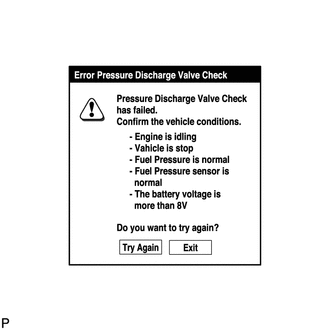
Turn the tester on.
Note
Confirm the following conditions:
-
Engine is idling.
-
Vehicle is stopped.
-
Fuel pressure is not extremely high (below 100000 kPa).
-
Fuel pressure sensor is normal.
-
Battery voltage is higher than 8 V.
-
-
Enter the following menus: Powertrain / Engine and ECT / Utility / Pressure Discharge Valve Check.
-
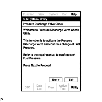
Press "Next".
-
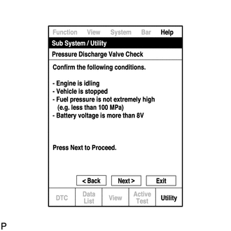
Press "Next" again to proceed.
-
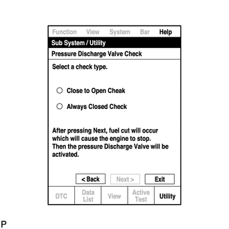
Select the "Pressure Discharge Valve Check" type.
Tech Tips
-
"Close to Open Check" opens the pressure discharge valve after the engine stops.
-
"Always Closed Check" holds the pressure discharge valve closed during the check.
-
-
Press "Next".
-
Perform troubleshooting based on the measurement results.
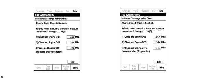
Tech Tips
-
During "Close to Open Check", if there is no large change in fuel pressure when the pressure discharge valve is closed while the engine is running and after the engine is stopped, and if the value is 0 kPa when the pressure discharge valve is open, the system is normal.
-
Perform "Always Closed Check" if the value is not 0 kPa when the pressure discharge valve is open during "Close to Open Check". If the results are the same as during "Close to Open Check", there is a pressure discharge valve operation malfunction.
-
If the fuel temperature is high, perform "Pressure Discharge Valve Check" after the fuel has cooled to the outside air temperature.
-
If a large amount of fuel is leaking, the fuel pressure decreases when the engine is stopped. However, the condition of the pressure discharge valve can still be determined by comparing the measurement results of "Close to Open Check" and "Always Closed Check".
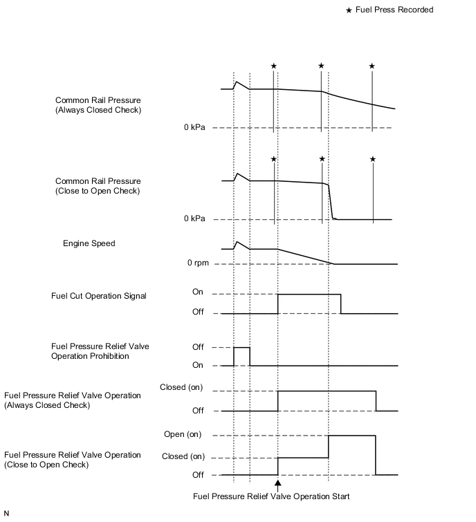
-
-
-