SFI SYSTEM VC Output Circuit
DESCRIPTION
The ECM constantly generates a 5 V power source voltage from the battery voltage supplied to the +B, +B2 (BATT) terminal to operate the microprocessor. The ECM also provides this power source voltage to the sensors through the VC output circuit.
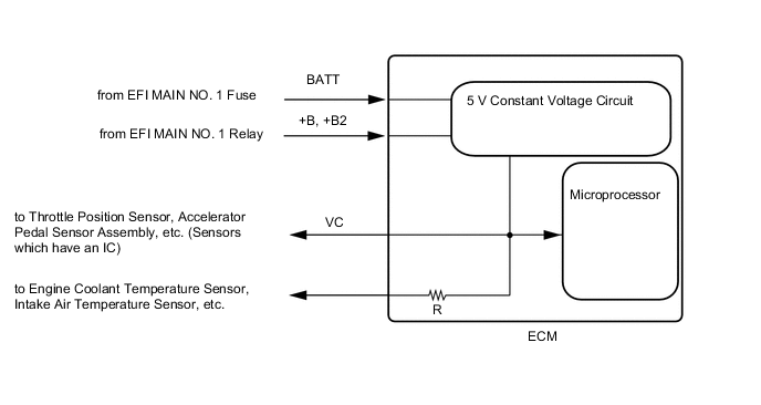
When the VC circuit is short-circuited, the microprocessor in the ECM and sensors that are supplied with power through the VC circuit are deactivated because the power is not supplied from the VC circuit. Under this condition, the system does not start up and the MIL does not illuminate even if the system malfunctions.
Tech Tips
Under normal conditions, the MIL is illuminated when the engine switch is turned on (IG). The MIL goes off when the engine is started.
WIRING DIAGRAM
-
For the circuit diagram of the ECM power source refer to the ECM power source circuit.
-
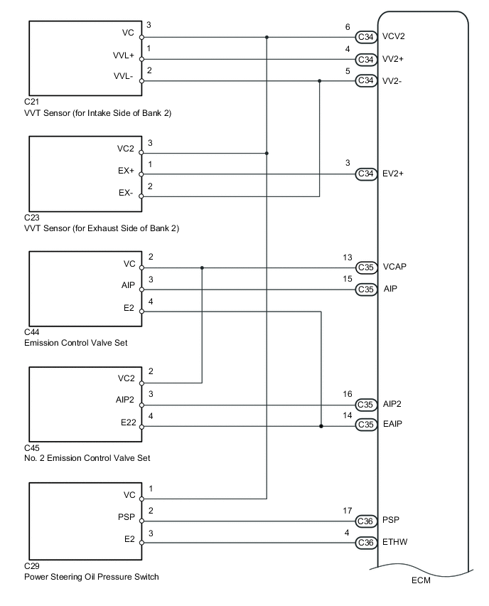
VC Power Source Circuit
Figure 1. for Automatic Transmission
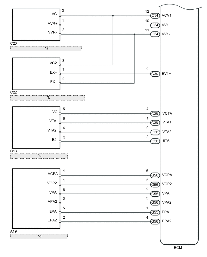
*a VVT Sensor (for Intake Side of Bank 1) *b VVT Sensor (for Exhaust Side of Bank 1) *c Throttle Body With Motor Assembly *d Accelerator Pedal Sensor Assembly Figure 2. for Manual Transmission
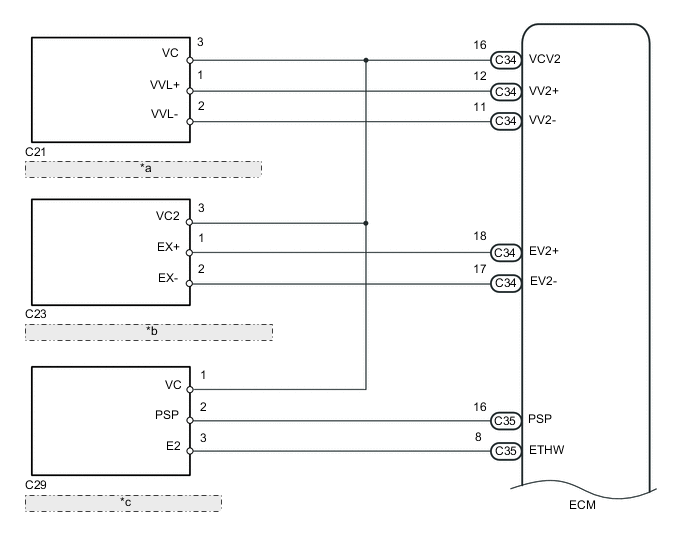
*a VVT Sensor (for Intake Side of Bank 2) *b VVT Sensor (for Exhaust Side of Bank 2) *c Power Steering Oil Pressure Switch 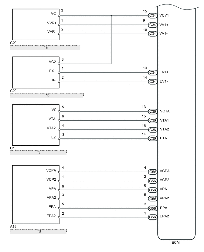
*a VVT Sensor (for Intake Side of Bank 1) *b VVT Sensor (for Exhaust Side of Bank 1) *c Throttle Body With Motor Assembly *d Accelerator Pedal Sensor Assembly
CAUTION / NOTICE / HINT
Note
Check the fuses for circuits related to this system before performing the following inspection procedure.
PROCEDURE
-
READ VALUE USING GTS
-
Connect the GTS to the DLC3.
-
Turn the engine switch on (IG).
-
Turn the GTS on.
-
Check the communication between the GTS and ECM.
Tech Tips
It can be checked using the "Engine" item of the Data List.
Result Result Proceed to Communication is not possible A Communication is possible B
B 
PROCEED TO NEXT SUSPECTED AREA SHOWN IN PROBLEM SYMPTOMS TABLE Click here
A 
-
-
CHECK TERMINAL VOLTAGE (POWER SOURCE OF ECM)
-
Turn the engine switch on (IG).
-
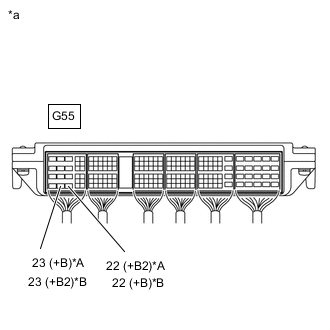
*A for Automatic Transmission *B for Manual Transmission *a Component with harness connected
(ECM)
Measure the voltage according to the value(s) in the table below.
Standard Voltage Tester Connection Switch Condition Specified Condition G55-23 (+B) - C36-12 (E1) Engine switch on (IG) 11 to 14 V G55-22 (+B2) - C36-12 (E1) Engine switch on (IG) 11 to 14 V Tech Tips
If the result is not as specified, since current is not flowing to the +B and +B2 terminals of the ECM, the system may not be started.
Result Proceed to OK NG
NG
GO TO ECM POWER SOURCE CIRCUIT Click here
OK
-
-
CHECK CONNECTION BETWEEN GTS AND ECM (THROTTLE POSITION SENSOR)
-
Disconnect the throttle body with motor assembly connector.
-
Turn the engine switch on (IG).
-
Turn the GTS on.
-
Check the communication between the GTS and ECM.
Tech Tips
It can be checked using the "Engine" item of the Data List.
Result Result Proceed to Communication is not possible A Communication is possible B Tech Tips
for Automatic Transmission
-
Perform "Inspection After Repair" after replacing the throttle body with motor assembly.
-
B
REPLACE THROTTLE WITH MOTOR BODY ASSEMBLY Click here
A
-
-
CHECK CONNECTION BETWEEN GTS AND ECM (ACCELERATOR PEDAL SENSOR)
-
Disconnect the accelerator pedal sensor assembly connector.
-
Turn the engine switch on (IG).
-
Turn the GTS on.
-
Check the communication between the GTS and ECM.
Tech Tips
It can be checked using the "Engine" item of the Data List.
Result Result Proceed to Communication is not possible A Communication is possible B
B
REPLACE ACCELERATOR PEDAL SENSOR ASSEMBLY Click here
A
-
-
CHECK CONNECTION BETWEEN GTS AND ECM (VVT SENSOR FOR INTAKE SIDE OF BANK 1)
-
Disconnect the VVT sensor (for intake side of bank 1) connector.
-
Turn the engine switch on (IG).
-
Turn the GTS on.
-
Check the communication between the GTS and ECM.
Tech Tips
It can be checked using the "Engine" item of the Data List.
Result Result Proceed to Communication is not possible A Communication is possible B
B
REPLACE VVT SENSOR (FOR INTAKE CAMSHAFT OF BANK 1) Click here
A
-
-
CHECK CONNECTION BETWEEN GTS AND ECM (VVT SENSOR FOR INTAKE SIDE OF BANK 2)
-
Disconnect the VVT sensor (for intake side of bank 2) connector.
-
Turn the engine switch on (IG).
-
Turn the GTS on.
-
Check the communication between the GTS and ECM.
Tech Tips
It can be checked using the "Engine" item of the Data List.
Result Result Proceed to Communication is not possible A Communication is possible B
B
REPLACE VVT SENSOR ((FOR INTAKE CAMSHAFT OF BANK 2)) Click here
A
-
-
CHECK CONNECTION BETWEEN GTS AND ECM (VVT SENSOR FOR EXHAUST SIDE OF BANK 1)
-
Disconnect the VVT sensor (for exhaust side of bank 1) connector.
-
Turn the engine switch on (IG).
-
Turn the GTS on.
-
Check the communication between the GTS and ECM.
Tech Tips
It can be checked using the "Engine" item of the Data List.
Result Result Proceed to MIL does not illuminate A MIL illuminates B
B
REPLACE VVT SENSOR (FOR EXHAUST CAMSHAFT OF BANK 1)) Click here
A
-
-
CHECK CONNECTION BETWEEN GTS AND ECM (VVT SENSOR FOR EXHAUST SIDE OF BANK 2)
-
Disconnect the VVT sensor (for exhaust side of bank 2) connector.
-
Turn the engine switch on (IG).
-
Turn the GTS on.
-
Check the communication between the GTS and ECM.
Tech Tips
It can be checked using the "Engine" item of the Data List.
Result Result Proceed to Communication is not possible A Communication is possible B
B
REPLACE VVT SENSOR (FOR EXHAUST CAMSHAFT OF BANK 2)) Click here
A
-
-
CHECK CONNECTION BETWEEN GTS AND ECM (POWER STEERING OIL PRESSURE SWITCH)
-
Disconnect the power steering oil pressure switch connector.
-
Turn the engine switch on (IG).
-
Turn the GTS on.
-
Check the communication between the GTS and ECM.
Tech Tips
It can be checked using the "Engine" item of the Data List.
Result Result Proceed to Communication is not possible (for Automatic Transmission) A Communication is not possible (for Manual Transmission) B Communication is possible C
B 
CHECK HARNESS AND CONNECTOR Click here
C
REPLACE POWER STEERING OIL PRESSURE SWITCH Click here
A
-
-
CHECK CONNECTION BETWEEN GTS AND ECM (EMISSION CONTROL VALVE SET)
-
Disconnect the emission control valve set connector.
-
Turn the engine switch on (IG).
-
Turn the GTS on.
-
Check the communication between the GTS and ECM.
Tech Tips
It can be checked using the "Engine" item of the Data List.
Result Result Proceed to Communication is not possible A Communication is possible B
B
REPLACE EMISSION CONTROL VALVE SET (FUEL PRESSURE SENSOR (FOR LOW PRESSURE SIDE)) Click here
A
-
-
CHECK CONNECTION BETWEEN GTS AND ECM (NO. 2 EMISSION CONTROL VALVE SET)
-
Disconnect the No. 2 emission control valve set connector.
-
Turn the engine switch on (IG).
-
Turn the GTS on.
-
Check the communication between the GTS and ECM.
Tech Tips
It can be checked using the "Engine" item of the Data List.
Result Result Proceed to Communication is not possible A Communication is possible B
B
REPLACE NO. 2 EMISSION CONTROL VALVE SET Click here
A
-
-
CHECK HARNESS AND CONNECTOR
-
Disconnect the throttle body with motor assembly connector.
-
Disconnect the accelerator pedal sensor assembly connector.
-
Disconnect the VVT sensor (for intake side of bank 1) connector.
-
Disconnect the VVT sensor (for intake side of bank 2) connector.
-
Disconnect the VVT sensor (for exhaust side of bank 1) connector.
-
Disconnect the VVT sensor (for exhaust side of bank 2) connector.
-
Disconnect the emission control valve set connector.
-
Disconnect the No. 2 emission control valve set connector.
-
Disconnect the ECM connectors.
-
Measure the resistance according to the value(s) in the table below.
Standard Resistance (Check for Short) Tester Connection Condition Specified Condition G56-6 (VCPA) - Body ground Always 10 kΩ or higher G56-3 (VCP2) - Body ground Always 10 kΩ or higher C36-2 (VCTA) - Body ground Always 10 kΩ or higher C35-13 (VCAP) - Body ground Always 10 kΩ or higher C34-12 (VCV1) - Body ground Always 10 kΩ or higher C34-6 (VCV2) - Body ground Always 10 kΩ or higher Result Proceed to OK NG
OK
REPLACE ECM Click here
NG
REPAIR OR REPLACE HARNESS OR CONNECTOR
-
-
CHECK HARNESS AND CONNECTOR
-
Disconnect the throttle body with motor assembly connector.
-
Disconnect the accelerator pedal sensor assembly connector.
-
Disconnect the VVT sensor (for intake side of bank 1) connector.
-
Disconnect the VVT sensor (for intake side of bank 2) connector.
-
Disconnect the VVT sensor (for exhaust side of bank 1) connector.
-
Disconnect the VVT sensor (for exhaust side of bank 2) connector.
-
Disconnect the ECM connectors.
-
Measure the resistance according to the value(s) in the table below.
Standard Resistance (Check for Short) Tester Connection Condition Specified Condition G56-4 (VCPA) -Body ground Always 10 kΩ or higher G56-2 (VCP2) -Body ground Always 10 kΩ or higher C36-13 (VCTA) -Body ground Always 10 kΩ or higher C34-15 (VCV1) -Body ground Always 10 kΩ or higher C34-16 (VCV2) -Body ground Always 10 kΩ or higher C88-18 (VCV2) - Body ground and other terminals Always 10 kΩ or higher C89-23 (VC) - Body ground and other terminals Always 10 kΩ or higher Result Proceed to OK NG
OK
REPLACE ECM Click here
NG
REPAIR OR REPLACE HARNESS OR CONNECTOR
-