SFI SYSTEM, Diagnostic DTC:P1613
| DTC Code | DTC Name |
|---|---|
| P1613 | Secondary Air Injection System Driver |
DESCRIPTION
Refer to DTC P0412 Click here.
| DTC No. | DTC Detection Condition | Trouble Area |
|---|---|---|
| P1613 | Either condition (1) or (2) is met: (1) All of conditions are met for 3 seconds or more (1 trip detection logic):
(2) Both conditions are met for 3 seconds or more (1 trip detection logic):
|
|
|
|
|
|
|
MONITOR DESCRIPTION
This DTC indicates an open or short circuit in the circuit containing the air pump assembly of the secondary air injection system. The air injection control driver performs diagnosis of the air pump assembly, emission control valve set and itself and sends the results of this diagnosis to the ECM as a duty signal. When the ECM receives a signal indicating a malfunction in the air pump assembly, an emission control valve set or the air injection control driver, it immediately illuminates the MIL and stores a DTC.
WIRING DIAGRAM
Refer to DTC P0412 Click here.
CAUTION / NOTICE / HINT
Note
Inspect the fuses of circuits related to this system before performing the following inspection procedure.
Tech Tips
-
By using the GTS to perform the Secondary Air Injection Check operation in the system check, the air-fuel ratio and the pressure in the secondary air injection system passage can be checked while the secondary air injection system is operating. This helps technicians to troubleshoot the system when it malfunctions.
-
Read freeze frame data using the GTS. Freeze frame data records the engine condition when malfunctions are detected. When troubleshooting, freeze frame data can help determine if the vehicle was moving or stationary, if the engine was warmed up or not, if the air-fuel ratio was lean or rich, and other data from the time the malfunction occurred.
PROCEDURE
-
CHECK AIR INJECTION CONTROL DRIVER (POWER SOURCE)
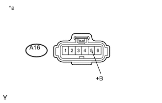
Text in Illustration *a Front view of wire harness connector
(to Air Injection Control Driver)
-
Disconnect the air injection control driver connector.
-
Measure the voltage according to the value(s) in the table below.
Standard Voltage Tester Connection Switch Condition Specified Condition A16-5 (+B) - Body ground Engine switch on (IG) 11 to 14 V (near battery voltage) -
Reconnect the air injection control driver connector.
NG 
REPAIR OR REPLACE HARNESS OR CONNECTOR
OK 
-
-
CHECK HARNESS AND CONNECTOR (AIR INJECTION CONTROL DRIVER - ECM)
-
Disconnect the air injection control driver connector.
-
Disconnect the ECM connector.
-
Measure the resistance according to the value(s) in the table below.
Standard Resistance (Check for Open) Tester Connection Condition Specified Condition C36-18 (AIRP) - A16-4 (SIP) Always Below 1 Ω C36-20 (AIRV) - A16-3 (SIV) Always Below 1 Ω C34-19 (AIDI) - A16-2 (DI) Always Below 1 Ω A16-1 (E) - Body ground Always Below 1 Ω Standard Resistance (Check for Short) Tester Connection Condition Specified Condition C36-18 (AIRP) or A16-4 (SIP) - Body ground Always 10 kΩ or higher C36-20 (AIRV) or A16-3 (SIV) - Body ground Always 10 kΩ or higher C34-19 (AIDI) or A16-2 (DI) - Body ground Always 10 kΩ or higher -
Reconnect the air injection control driver connector.
-
Reconnect the ECM connector.
NG
REPAIR OR REPLACE HARNESS OR CONNECTOR
OK
-
-
CHECK AIR INJECTION CONTROL DRIVER (DI TERMINAL VOLTAGE)
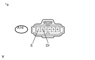
Text in Illustration *a Front view of wire harness connector
(to Air Injection Control Driver)
-
Disconnect the air injection control driver connector.
-
Measure the voltage according to the value(s) in the table below.
Standard Voltage Tester Connection Switch Condition Specified Condition A16-2 (DI) - A16-1 (E) Engine switch on (IG) 11 to 14 V (near battery voltage) -
Reconnect the air injection control driver connector.
NG
REPLACE ECM Click here
OK
-
-
PERFORM ACTIVE TEST USING INTELLIGENT TESTER
-
Disconnect the air injection control driver connector.
-
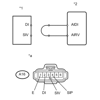
Text in Illustration *1 Air Injection Control Driver *2 ECM *a Front view of wire harness connector
(to Air Injection Control Driver)
Connect terminals DI and SIV of the wire harness connector for the air injection control driver.
-
Connect the GTS to the DLC3.
-
Turn the engine switch on (IG) and turn the GTS on.
-
Enter the following menus: Powertrain / Engine and ECT / Utility / Secondary Air Injection Check / Manual Mode / AIR PUMP: ON, ASV: OPEN.
Tech Tips
When Manual Mode is selected, the GTS initialization (atmospheric pressure measurement) is performed automatically. The initialization takes 10 seconds. After the initialization, AIR PUMP and ASV operation can be selected.
-
Start the engine.
-
Perform the AIR system intrusive operation while the engine is idling.
-
Measure the voltage between the SIV and E terminals of the ECM connector when the AIR system is ON and OFF.
-
Turn the engine switch off.
Note
-
Do not perform the System Check operation repetitively. It may cause the damage in the system. If necessary, leave an interval of several minutes between System Check operations.
-
When performing the Secondary Air Injection Check operation after the battery cable has been reconnected, wait for 7 minutes with the engine switch on (IG) or the engine running.
-
Turn the engine switch off when the Secondary Air Injection Check operation finishes.
Standard Voltage Tester Connection Condition Specified Condition A16-3 (SIV) - A16-1 (E) AIR PUMP: ON, ASV: OPEN 0.5 to 2 V A16-3 (SIV) - A16-1 (E) AIR PUMP: OFF, ASV: CLOSE 11 to 14 V -
-

Text in Illustration *1 Air Injection Control Driver *2 ECM *a Front view of wire harness connector
(to Air Injection Control Driver)
Connect terminals DI and SIP of the wire harness connector for the air injection control driver.
-
Connect the GTS to the DLC3.
-
Turn the engine switch on (IG) and turn the GTS on.
-
Enter the following menus: Powertrain / Engine and ECT / Utility / Secondary Air Injection Check / Manual Mode / AIR PUMP: ON, ASV: OPEN.
Tech Tips
When Manual Mode is selected, the GTS initialization (atmospheric pressure measurement) is performed automatically. The initialization takes 10 seconds. After the initialization, AIR PUMP and ASV operation can be selected.
-
Start the engine.
-
Perform the AIR system intrusive operation while the engine is idling.
-
Measure the voltage between the SIP and E terminals of the ECM connector when the AIR system is ON and OFF.
-
Turn the engine switch off.
Note
-
Do not perform the System Check operation repetitively. It may cause the damage in the system. If necessary, leave an interval of several minutes between System Check operations.
-
When performing the Secondary Air Injection Check operation after the battery cable has been reconnected, wait for 7 minutes with the engine switch on (IG) or the engine running.
-
Turn the engine switch off when the Secondary Air Injection Check operation finishes.
Standard Voltage Tester Connection Condition Specified Condition A16-4 (SIP) - A16-1 (E) AIR PUMP: ON, ASV: OPEN 0.5 to 2 V A16-4 (SIP) - A16-1 (E) AIR PUMP: OFF, ASV: CLOSE 11 to 14 V -
-
Reconnect the air injection control driver connector.
NG
REPLACE ECM Click here
OK
-
-
REPLACE AIR INJECTION CONTROL DRIVER
-
Replace the air injection control driver Click here.
NEXT
-
-
CONFIRM WHETHER DTC OUTPUT RECURS
-
Start the engine and warm it up.
-
Turn the engine switch off.
-
Connect the GTS to the DLC3.
-
Turn the engine switch on (IG) and turn the GTS on.
-
Clear DTCs Click here.
-
Enter the following menus: Powertrain / Engine and ECT / Utility / Secondary Air Injection Check / Automatic Mode.
-
Start the engine after the GTS initialization is finished.
-
Perform the system check operation by pressing Enter.
-
After operating the AIR system, press the Enter button to confirm the AIR system pending codes.
-
Read DTCs.
Result Result Proceed to No output A Other DTCs B -
Turn the engine switch off.
Note
-
When performing the Secondary Air Injection Check operation after the battery cable is reconnected, wait for 7 minutes with the engine switch on (IG) or the engine running.
-
Turn the engine switch off when the Secondary Air Injection Check operation finishes.
-
A
END
B
REPLACE ECM Click here
-