SFI SYSTEM, Diagnostic DTC:P0112, P0113
| DTC Code | DTC Name |
|---|---|
| P0112 | Intake Air Temperature Circuit Low Input |
| P0113 | Intake Air Temperature Circuit High Input |
DESCRIPTION
-
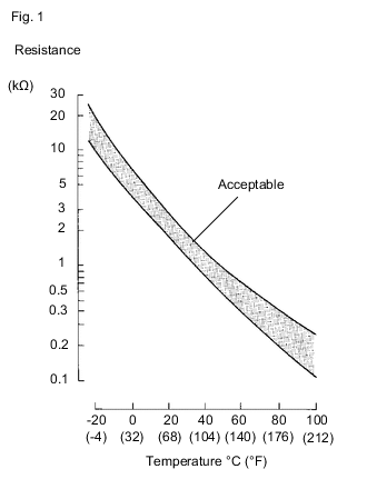
The intake air temperature sensor, mounted on the mass air flow meter, monitors the intake air temperature. The intake air temperature sensor has a built-in thermistor with a resistance that varies according to the temperature of the intake air. When the intake air temperature is low, the resistance of the thermistor increases. When the temperature is high, the resistance drops. These variations in resistance are transmitted to the ECM as voltage changes (see Fig. 1).
-
The intake air temperature sensor is powered by a 5 V supply from the THA terminal of the ECM, via resistor R.
-
Resistor R and the intake air temperature sensor are connected in series. When the resistance value of the intake air temperature sensor changes according to changes in the intake air temperature, the voltage at terminal THA also varies. Based on this signal, the ECM increases the fuel injection volume when the engine is cold to improve driveability.
Tech Tips
When DTC P0112 or P0113 is stored, the ECM enters fail-safe mode. During fail-safe mode, the intake air temperature is estimated to be 20°C (68°F) by the ECM. The ECM continues operating fail-safe mode until a pass condition is detected.
| DTC No. | DTC Detection Condition | Trouble Area |
|---|---|---|
| P0112 | A short in the intake air temperature sensor circuit for 0.5 seconds (1 trip detection logic). |
|
| P0113 | An open in the intake air temperature sensor circuit for 0.5 seconds (1 trip detection logic). |
|
Tech Tips
When either any of these DTCs are output, check the intake air temperature by entering the following menus: Powertrain / Engine and ECT / Data List / Intake Air.
| GTS Display | Malfunction |
|---|---|
| -40°C (-40°F) | Open circuit |
| 140°C (284°F) or higher | Short circuit |
MONITOR DESCRIPTION
The ECM monitors the sensor voltage and uses this value to calculate the intake air temperature. When the sensor output voltage deviates from the normal operating range, the ECM interprets this as a malfunction in the intake air temperature sensor and stores a DTC.
Example:
If the sensor output voltage is higher than 4.91 V for 0.5 seconds or more, the ECM determines that there is an open circuit in the intake air temperature sensor circuit and stores DTC P0113. Conversely, if the output voltage is below 0.18 V for 0.5 seconds or more, the ECM determines that there is a short in the sensor circuit and stores DTC P0112.
If the malfunction is not repaired successfully, a DTC is stored 0.5 seconds after the engine is next started.
WIRING DIAGRAM
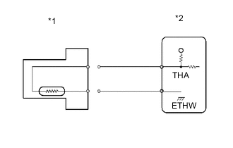
- for Automatic Transmission
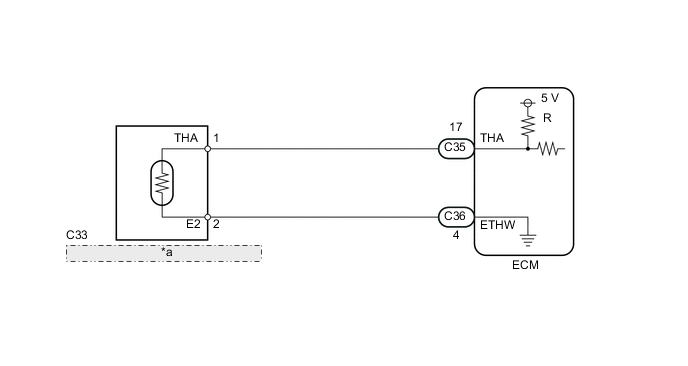
| *a | Intake Air Temperature Sensor (Built into Mass Air Flow Meter) |
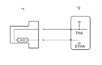
- for Manual Transmission
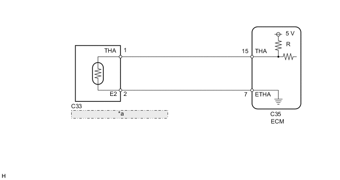
| *a | Intake Air Temperature Sensor (Built into Mass Air Flow Meter) |
CAUTION / NOTICE / HINT
Tech Tips
Read freeze frame data using the GTS. Freeze frame data records the engine condition when malfunctions are detected. When troubleshooting, freeze frame data can help determine if the vehicle was moving or stationary, if the engine was warmed up or not, if the air fuel ratio was lean or rich, and other data from the time the malfunction occurred.
PROCEDURE
-
READ VALUE USING GTS (INTAKE AIR TEMPERATURE)
-
Connect the GTS to the DLC3.
-
Turn the engine switch on (IG).
-
Turn the GTS on.
-
Enter the following menus: Powertrain / Engine and ECT / Data List / Intake Air.
-
Read the value displayed on the GTS.
Result Result Proceed to -40°C (-40°F) A 140°C (284°F) or higher B Same as actual intake air temperature C Tech Tips
-
If there is an open circuit, the GTS indicates -40°C (-40°F).
-
If there is a short circuit, the GTS indicates 140°C (284°F) or higher.
-
B 
READ VALUE USING GTS (CHECK FOR SHORT IN WIRE HARNESS) Click here
C 
CHECK FOR INTERMITTENT PROBLEMS Click here
A 
-
-
READ VALUE USING GTS (CHECK FOR OPEN IN WIRE HARNESS)

-
Disconnect the mass air flow meter connector.
-
Connect terminals 1 (THA) and 2 (E2) of the mass air flow meter wire harness side connector.
-
Connect the GTS to the DLC3.
-
Turn the engine switch on (IG).
-
Turn the GTS on.
-
Enter the following menus: Powertrain / Engine and ECT / Data List / Intake Air.
-
Read the value displayed on the GTS.
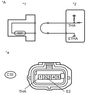
Standard value 140°C (284°F) or higher Text in Illustration *A for Manual Transmission *B for Automatic Transmission *1 Mass Air Flow Meter *2 ECM *a Front view of wire harness connector
(to Mass Air Flow Meter)
-
Reconnect the mass air flow meter connector.
Tech Tips
for Automatic TransmissionPerform "Inspection After Repair" after replacing the mass air flow meter sub-assembly Click here.
OK
CONFIRM GOOD CONNECTION TO SENSOR. IF OK, REPLACE MASS AIR FLOW METER Click here
NG
-
-
CHECK HARNESS AND CONNECTOR (MASS AIR FLOW METER - ECM)
-
Disconnect the mass air flow meter connector.
-
Disconnect the ECM connector.
-
Measure the resistance according to the value(s) in the table below.
Standard Resistance for Automatic Transmission Tester Connection Condition Specified Condition C33-1 (THA) - C35-17 (THA) Always Below 1 Ω C33-2 (E2) - C36-4 (ETHW) Always Below 1 Ω for Manual Transmission Tester Connection Condition Specified Condition C33-1 (THA) - C35-15 (THA) Always Below 1 Ω C33-2 (E2) - C35-7 (ETHA) Always Below 1 Ω -
Reconnect the mass air flow meter connector.
-
Reconnect the ECM connector.
OK
CONFIRM GOOD CONNECTION TO ECM. IF OK, REPLACE ECM Click here
NG
REPAIR OR REPLACE HARNESS OR CONNECTOR
-
-
READ VALUE USING GTS (CHECK FOR SHORT IN WIRE HARNESS)
-
Disconnect the mass air flow meter connector.
-
Connect the GTS to the DLC3.
-
Turn the engine switch on (IG).
-
Turn the GTS on.
-
Enter the following menus: Powertrain / Engine and ECT / Data List / Intake Air.
-
Read the value displayed on the GTS.
Standard value -40°C (-40°F) Text in Illustration *A for Manual Transmission *B for Automatic Transmission *1 Mass Air Flow Meter *2 ECM -
Reconnect the mass air flow meter connector.
Tech Tips
for Automatic TransmissionPerform "Inspection After Repair" after replacing the mass air flow meter sub-assembly Click here.
OK
REPLACE MASS AIR FLOW METER Click here
NG
-
-
CHECK HARNESS AND CONNECTOR (MASS AIR FLOW METER - ECM)
-
Disconnect the mass air flow meter connector.
-
Disconnect the ECM connector.
-
Measure the resistance according to the value(s) in the table below.
Standard Resistance for Automatic Transmission Tester Connection Condition Specified Condition C33-1 (THA) or C35-17 (THA) - Body ground Always 10 kΩ or higher for Manual Transmission Tester Connection Condition Specified Condition C33-1 (THA) or C35-15 (THA) - Body ground Always 10 kΩ or higher -
Reconnect the mass air flow meter connector.
-
Reconnect the ECM connector.
OK
REPLACE ECM Click here
NG
REPAIR OR REPLACE HARNESS OR CONNECTOR
-