GLOW PLUG INSTALLATION
PROCEDURE
-
INSTALL GLOW PLUG
Note
-
Measure the resistance of the glow plug when reinstalling it. If the result is not as specified, replace the glow plug with a new one.
-
Replace the glow plug with a new one when it has been dropped or subjected to a physical impact.
-
Remove any carbon deposits from the glow plug hole when reinstalling the glow plug.
-
Clean the glow plug hole.
-
Wrap tape around a drill bit with a diameter of 4.4 mm (0.173 in.), 118.5 mm (4.665 in.) from its tip.
-
Insert the drill bit 118.5 mm (4.665 in.) into the glow plug hole (up to the tape) and remove any carbon deposits by turning the drill bit by hand.
-
Insert a drill bit with a diameter of 4 mm (0.157 in.) into the glow plug hole and remove any carbon deposits from the end of the glow plug hole by turning the drill bit by hand.
-
Using a 12 mm deep socket wrench, install the glow plug assembly.
- Torque:
- 18 N*m { 178 kgf*cm, 13 ft.*lbf }
Note
Do not use any tools, such as air tools, which are liable to cause an impact to the glow plugs when installing them.
-
-
Install the 4 glow plugs.
- Torque:
- 13 N*m { 133 kgf*cm, 10 ft.*lbf }
Note
Do not use any tools, such as air tools, which are liable to cause an impact to the glow plugs when installing them.
-
-
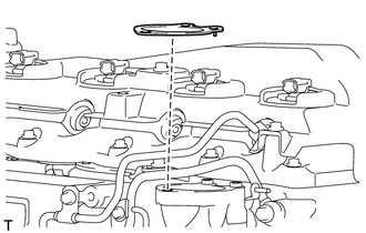
INSTALL NO. 1 INTAKE MANIFOLD INSULATOR
-
INSTALL NO. 1 GLOW PLUG CONNECTOR
-
Temporarily install the No. 1 glow plug connector with the 4 nuts.
-
Tighten the 4 nuts.
- Torque:
- 2.2 N*m { 22 kgf*cm, 19 in.*lbf }
-
Install the 4 screw grommets.
-
Connect the wire harness to the No. 1 glow plug connector with the nut.
- Torque:
- 2.6 N*m { 27 kgf*cm, 23 in.*lbf }
-
Install the screw grommet.
-
-
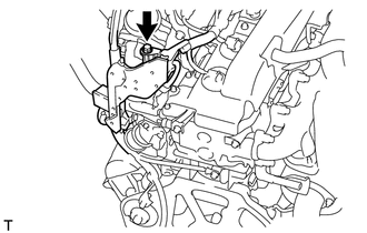
INSTALL NO. 2 MANIFOLD STAY
-
Install the No. 2 manifold stay with the bolt.
- Torque:
- 20 N*m { 204 kgf*cm, 15 ft.*lbf }
-
-
INSTALL INTAKE PIPE STAY
-
INSTALL INTAKE AIR CONNECTOR WITH DIESEL THROTTLE BODY ASSEMBLY (w/o EGR System)
-
Set a new gasket on the intake manifold.
Note
Make sure the claw of the gasket face the intake manifold as shown in the illustration.
-
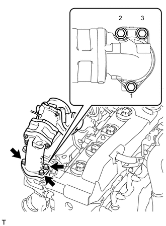
Install the intake air connector with diesel throttle body with the 3 bolts.
- Torque:
- 20 N*m { 204 kgf*cm, 15 ft.*lbf }
Note
Tighten the bolts in the order shown in the illustration.
-
Connect the throttle position sensor connector.
-
-
INSTALL AIR CONNECTOR STAY (w/o EGR System)
-
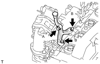
Temporarily install the air connector stay with the 3 bolts.
-
Tighten the bolt labeled A.
- Torque:
- 20 N*m { 204 kgf*cm, 15 ft.*lbf }
-
Tighten the 2 bolts labeled B.
- Torque:
- 20 N*m { 204 kgf*cm, 15 ft.*lbf }
-
-
CONNECT ENGINE WIRE (w/o EGR System)
-
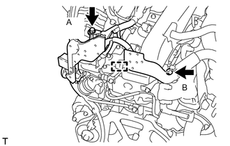
for LHD:
Connect the engine wire with the clamp and install the 2 bolts.
- Torque:
- for bolt A
- 13 N*m { 131 kgf*cm, 9 ft.*lbf }
- for bolt B
- 22 N*m { 220 kgf*cm, 16 ft.*lbf }
-
for RHD:
Connect the engine wire with the bolt.
- Torque:
- 13 N*m { 131 kgf*cm, 9 ft.*lbf }
-
-
INSTALL NO. 1 NO. 2 AND NO. 3 INJECTION PIPE SUB-ASSEMBLY (w/o EGR System)
-
INSTALL THROTTLE BODY BRACKET (w/o EGR System)
-
Install the throttle body bracket with the 2 bolts.
- Torque:
- 20 N*m { 204 kgf*cm, 15 ft.*lbf }
-
Install the gas filter with gas filter bracket with the bolt.
- Torque:
- 20 N*m { 204 kgf*cm, 15 ft.*lbf }
-
Connect the vacuum hose.
-
-
INSTALL NO. 1 INTAKE PIPE (w/o EGR System)
-
INSTALL NO. 4 VACUUM TRANSMITTING PIPE SUB-ASSEMBLY (w/o EGR System)
-
INSTALL INLET HEATER WATER HOSE (w/o EGR System)
-
INSTALL ELECTRIC EGR CONTROL VALVE ASSEMBLY (w/ EGR System)
-
Install the electric EGR control valve Click here.
-
-
CONNECT CABLE TO NEGATIVE BATTERY TERMINAL
Note
When disconnecting the cable, some systems need to be initialized after the cable is reconnected Click here.
-
BLEED AIR FROM FUEL SYSTEM
-
INSPECT FOR FUEL LEAK
-
INSPECT FOR COOLANT LEAK