THERMOSTAT INSTALLATION
PROCEDURE
-
INSTALL THERMOSTAT
-
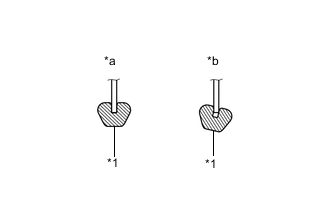
Text in Illustration *1 Gasket *a CORRECT *b INCORRECT Install a new gasket to the thermostat as shown in the illustration.
Note
When installing the gasket to the thermostat, be careful not to deform the gasket. Make sure that the groove of the gasket is properly installed to the thermostat as shown in the illustration.
-
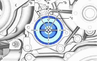
Text in Illustration *a Upward *b 30° *c Jiggle Valve Insert the thermostat into the engine water pump assembly with the jiggle valve facing straight upward.
Tech Tips
The jiggle valve may be set to within 30° on either side of the prescribed position.
-
-
INSTALL WATER INLET
-
Install the water inlet with the 3 bolts.
- Torque:
- 13 N*m { 133 kgf*cm, 10 ft.*lbf }
-
-
CONNECT NO. 2 RADIATOR HOSE
-
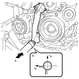
Text in Illustration *a Upper Side *b Right Side of Vehicle Connect the No. 2 radiator hose to the water inlet and slide the hose clamp to secure the hose as shown in the illustration.
-
-
CONNECT NO. 2 WATER BY-PASS PIPE SUB-ASSEMBLY
-
Connect the No. 2 water by-pass pipe sub-assembly to the engine water pump assembly and water inlet with the 2 bolts.
- Torque:
- 10 N*m { 102 kgf*cm, 7 ft.*lbf }
-
-
INSTALL WATER HOSE SUB-ASSEMBLY (for Cold Area Specification Vehicles)
-
Connect the water hose sub-assembly to the viscous heater with magnet clutch and heater pipes, and install the bolt.
- Torque:
- 9.8 N*m { 100 kgf*cm, 87 in.*lbf }
-
Slide the 4 hose clamps to secure the water hose sub-assembly.
-
-
INSTALL FAN SHROUD