WATER PUMP INSTALLATION
PROCEDURE
-
INSTALL ENGINE WATER PUMP ASSEMBLY
-
Temporarily install a new gasket and the water pump assembly without cover to the water pump cover with the bolt.
-
Temporarily install a new gasket and the engine water pump assembly to the cylinder block sub-assembly with the 2 nuts and 5 bolts.
-
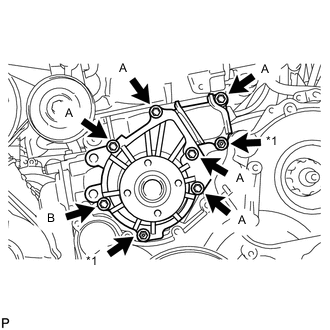
Text in Illustration *1 Nut Fully tighten the 5 bolts A and the 2 nuts.
- Torque:
- 13 N*m { 133 kgf*cm, 10 ft.*lbf }
-
Fully tighten the bolt B.
- Torque:
- 9.1 N*m { 93 kgf*cm, 81 in.*lbf }
-
-
INSTALL CYLINDER BLOCK INSULATOR
-
INSTALL NO. 2 TIMING BELT COVER
-
INSTALL NO. 1 TIMING BELT IDLER SUB-ASSEMBLY
-
INSTALL CAMSHAFT TIMING PULLEY
-
INSTALL TIMING BELT
-
INSTALL NO. 1 TIMING BELT COVER
-
INSTALL CYLINDER HEAD COVER SUB-ASSEMBLY
-
INSTALL VENTILATION PIPE
-
INSTALL NO. 1 COMPRESSOR MOUNTING BRACKET
-
INSTALL GENERATOR ASSEMBLY
-
INSTALL GENERATOR BRACKET
-
CONNECT COMPRESSOR AND MAGNETIC CLUTCH (w/ Air Conditioning System)
-
INSTALL NO. 1 VISCOUS HEATER BRACKET SUB-ASSEMBLY (for Cold Area Specification Vehicles)
-
INSTALL VISCOUS WITH MAGNET CLUTCH HEATER ASSEMBLY (for Cold Area Specification Vehicles)
-
INSTALL COMPRESSOR OUTLET ELBOW
-
INSTALL AIR CLEANER CASE SUB-ASSEMBLY
-
INSTALL AIR CLEANER FILTER ELEMENT SUB-ASSEMBLY
-
INSTALL AIR CLEANER CAP SUB-ASSEMBLY
-
INSTALL NO. 1 AIR CLEANER HOSE
-
INSTALL FAN SHROUD
-
Install the fan pulley to the engine water pump assembly.
-
Install the No. 2 water by-pass hose to the water inlet.
-
Temporarily install the shroud together with the coupling fan to the engine water pump assembly with the 4 nuts. Tighten the nuts as much as possible by hand.
-
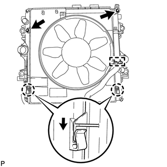
Attach the claws of the shroud to the radiator as shown in the illustration.
-
Install the fan shroud to the radiator with the 2 bolts.
- Torque:
- 5.0 N*m { 51 kgf*cm, 44 in.*lbf }
-
Install the fan and generator V belt Click here.
-
Install the fan with fluid coupling assembly to the engine water pump assembly with the 4 nuts.
- Torque:
- 23 N*m { 235 kgf*cm, 17 ft.*lbf }
-
Attach the No. 2 water by-pass hose to the clamp on the fan shroud.
-
for Automatic Transmission:
-
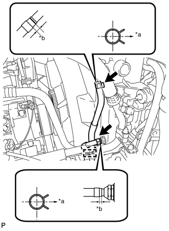
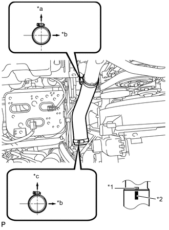
Text in Illustration *a RH Side *b 2 to 7 mm Connect the 2 oil cooler hoses.
Tech Tips
-
Position the hose clamps as shown in the illustration.
-
Position the clips so that the distance from the end of hose is 2 to 7 mm (0.0787 to 0.275 in.).
-
-
Attach the 2 oil cooler hoses to the clamp on the fan shroud.
-
-
Connect the No. 2 water by-pass hose to the radiator reservoir.
-
Connect the No. 1 water by-pass hose to the fan shroud and attach the 2 clamps.
-
Install the radiator reservoir assembly with the 3 bolts.
- Torque:
- 5.0 N*m { 51 kgf*cm, 44 in.*lbf }
-
-
INSTALL INTERCOOLER AIR HOSE
Note
Before installation, remove any oil residue from the inside of the inlet pipe and intercooler.
-
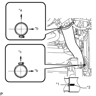
Text in Illustration *1 Embossed Mark *2 Paint Mark *a Rear Side of Vehicle *b LH Side *c Upper Align the paint mark of the intercooler air hose with the embossed mark of the intake pipe.
-
Tighten the 2 clamps.
- Torque:
- 6.5 N*m { 66 kgf*cm, 58 in.*lbf }
-
Connect the vacuum transmitting hose.
-
-
INSTALL NO. 1 AIR HOSE
Note
Before installation, remove any oil residue from the inside of the inlet pipe and intercooler.
-
Text in Illustration *1 Embossed Mark *2 Paint Mark *a Rear Side of Vehicle *b LH Side *c Upper Align the paint mark of the intercooler air hose with the embossed mark of the intercooler.
-
Tighten the 2 clamps.
- Torque:
- 6.5 N*m { 66 kgf*cm, 58 in.*lbf }
-
-
INSTALL NO. 1 RADIATOR HOSE
-
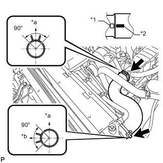
Text in Illustration *1 Protrusion *2 Paint Mark *a Upper *b LH Side Install the radiator hose and attach the clamp.
Tech Tips
Make sure the direction of the hose clamp is as shown in the illustration.
-
-
INSTALL FRONT HEATER BRACKET (for Cold Area Specification Vehicles)
-
INSTALL NO. 3 ENGINE WIRE (for Cold Area Specification Vehicles)
-
Install the 2 nuts to the battery terminals.
- Torque:
- 7.5 N*m { 76 kgf*cm, 66 in.*lbf }
-
Attach the 3 wire harness clamps to the fan shroud.
-
-
INSTALL NO. 2 CYLINDER HEAD COVER SUB-ASSEMBLY
-
INSTALL NO. 4 INJECTION PIPE SUB-ASSEMBLY
-
INSTALL MANIFOLD STAY WITH VACUUM SWITCHING VALVE
-
INSTALL INTAKE AIR CONNECTOR WITH DIESEL THROTTLE BODY ASSEMBLY (w/o EGR System)
-
CONNECT ENGINE WIRE (w/o EGR System)
-
INSTALL AIR CONNECTOR STAY (w/o EGR System)
-
INSTALL NO. 1, NO. 2 AND NO. 3 INJECTION PIPE (w/o EGR System)
-
INSTALL THROTTLE BODY BRACKET (w/o EGR System)
-
INSTALL NO. 1 INTAKE PIPE (w/o EGR System)
-
INSTALL NO. 4 VACUUM TRANSMITTING PIPE SUB-ASSEMBLY (w/o EGR System)
-
INSTALL INLET HEATER WATER HOSE (w/o EGR System)
-
INSTALL ELECTRIC EGR CONTROL VALVE ASSEMBLY (w/ EGR System)
-
Install the electric EGR control valve assembly Click here.
-
-
CONNECT CABLE TO NEGATIVE BATTERY TERMINAL
Note
When disconnecting the cable, some systems need to be initialized after the cable is reconnected Click here.
-
ADD ENGINE COOLANT
-
BLEED AIR FROM FUEL SYSTEM
-
INSPECT FOR ENGINE COOLANT LEAK
-
INSPECT FOR FUEL LEAK
-
INSTALL ENGINE REAR UNDER COVER ASSEMBLY
-
INSTALL NO. 1 ENGINE UNDER COVER SUB-ASSEMBLY
-
INSTALL FRONT BUMPER LOWER COVER
-
INSTALL UPPER RADIATOR SUPPORT SEAL