RADIATOR INSTALLATION
PROCEDURE
-
INSTALL NO. 1 RADIATOR TO SUPPORT SEAL
-
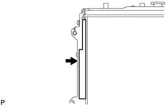
Install the seal to the radiator assembly as shown in the illustration.
-
-
INSTALL NO. 2 RADIATOR TO SUPPORT SEAL
-
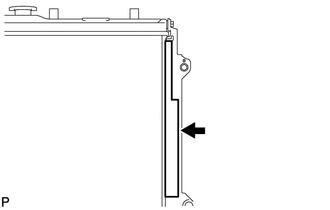
Install the seal to the radiator assembly as shown in the illustration.
-
-
INSTALL RADIATOR ASSEMBLY
-
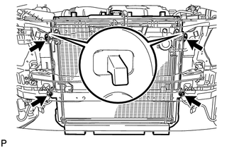
Insert the radiator bracket hooks into the radiator support holes.
-
Install the radiator with the 4 bolts.
- Torque:
- 18 N*m { 184 kgf*cm, 13 ft.*lbf }
-
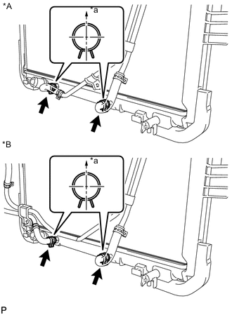
Text in Illustration *A w/ Warmer *B w/ Air Cooled Transmission Oil Cooler *a Upper for Automatic Transmission:
Connect the 2 oil cooler hoses.
Tech Tips
Make sure the direction of the hose clamp is as shown in the illustration.
-
-
INSTALL FAN SHROUD
-
Install the fan pulley to the water pump.
-
Place the shroud together with the coupling fan between the radiator and engine.
Note
Be careful not to damage the radiator core.
-
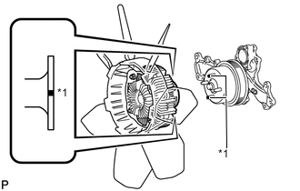
Text in Illustration *1 Paint Mark Align the paint marks on the heads of the water pump stud bolts with the paint marks of the same color on the outer edge of the fluid coupling flange and install the fluid coupling to the water pump.
-
Temporarily install the fluid coupling fan to the water pump with the 4 nuts. Tighten the nuts as much as possible by hand.
-
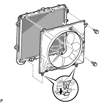
Attach the claws of the shroud to the radiator as shown in the illustration.
-
Install the shroud with the 2 bolts.
- Torque:
- 5.0 N*m { 51 kgf*cm, 44 in.*lbf }
-
Install the fan and generator V-belt Click here.
-
Tighten the 4 nuts of the fluid coupling fan.
- Torque:
- 21 N*m { 214 kgf*cm, 15 ft.*lbf }
-
-
CONNECT OIL COOLER TUBE (w/ Air Cooled Transmission Oil Cooler)
-
Connect the oil cooler tube with the 2 bolts, and attach the claw to close the flexible hose clamp.
- Torque:
- 5.5 N*m { 56 kgf*cm, 49 in.*lbf }
-
-
CONNECT OIL COOLER TUBE (w/ Warmer)
-
Connect the oil cooler tube with the 2 bolts, and attach the claw to close the flexible hose clamp.
- Torque:
- 5.5 N*m { 56 kgf*cm, 49 in.*lbf }
-
-
INSTALL RADIATOR RESERVOIR
-
Install the radiator reservoir with the 3 bolts.
- Torque:
- 5.0 N*m { 51 kgf*cm, 44 in.*lbf }
-
Connect the reservoir hose to upper side of the radiator tank upper.
-
-
INSTALL NO. 2 RADIATOR HOSE
-
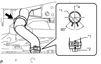
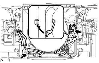
Text in Illustration *1 Paint Mark *2 Protrusion *a Upper Connect the No. 2 radiator hose so that its paint mark aligns with the radiator protrusion as shown in the illustration.
Tech Tips
-
Make sure the paint mark of the No. 1 air injection system hose is facing upward.
-
Make sure the direction of the hose clamp is as shown in the illustration.
-
-
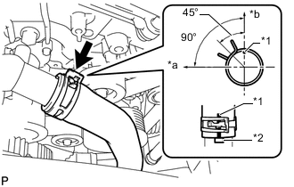
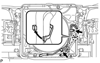
Text in Illustration *1 Paint Mark *2 Protrusion *a Front *b Upper Connect the No. 2 radiator hose so that its paint mark aligns with the water inlet housing protrusion as shown in the illustration.
Tech Tips
-
Make sure the paint mark of the No. 1 air injection system hose is facing upward.
-
Make sure the direction of the hose clamp is as shown in the illustration.
-
-
-
INSTALL NO. 1 RADIATOR HOSE
-
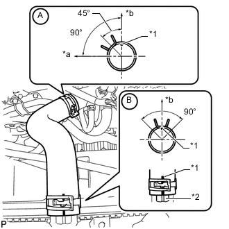
Text in Illustration *1 Paint Mark *2 Protrusion *a Front *b Upper Connect the No. 1 radiator hose to the water inlet housing shown in the illustration labeled A.
Tech Tips
-
Make sure the paint mark of the No. 1 radiator hose is facing upward.
-
Make sure the direction of the hose clamp is as shown in the illustration.
-
-
Connect the No. 1 radiator hose so that its paint mark aligns with the radiator protrusion as shown in the illustration labeled B.
Tech Tips
-
Make sure the paint mark of the No. 1 radiator hose is facing upward.
-
Make sure the direction of the hose clamp is as shown in the illustration.
-
-
-
INSTALL RADIATOR SIDE DEFLECTOR LH
-
Attach the 3 claws.
-
Install the deflector with the clip.
-
-
INSTALL RADIATOR SIDE DEFLECTOR RH
-
Attach the 3 claws.
-
Install the deflector with the clip.
-
-
INSTALL UPPER FRONT BUMPER RETAINER
-
Install the retainer with the 3 bolts.
- Torque:
- 8.0 N*m { 82 kgf*cm, 71 in.*lbf }
-
-
INSTALL FRONT BUMPER COVER
-
Install the front bumper cover Click here.
-
-
ADD ENGINE COOLANT
-
INSPECT FOR ENGINE COOLANT LEAK
-
INSTALL NO. 1 ENGINE UNDER COVER SUB-ASSEMBLY
-
INSTALL FRONT BUMPER COVER LOWER
-
INSTALL V-BANK COVER
-
INSTALL UPPER RADIATOR SUPPORT SEAL