INTAKE MANIFOLD INSTALLATION
PROCEDURE
-
INSTALL INTAKE MANIFOLD
-
Install the purge line hose to the intake manifold, and slide the clip to secure the hose.
-
Install the 2 wire harness clamp brackets to the intake manifold with the 2 bolts.
- Torque:
- 8.0 N*m { 82 kgf*cm, 71 in.*lbf }
-
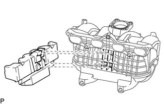
Install the intake manifold insulator to the intake manifold.
Tech Tips
Insert the protrusions of the intake manifold insulator into the grille of the intake manifold.
Note
Insert the intake manifold insulator until the position of the line as shown in the illustration.
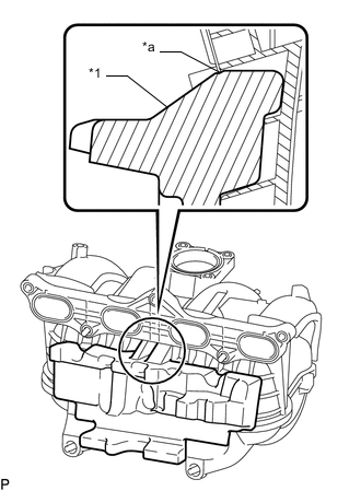
Text in Illustration *1 Intake Manifold Insulator *a Line -
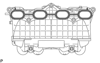
Install a new gasket to the intake manifold.
-
Install the intake manifold with the 5 bolts and 2 nuts.
- Torque:
- 25 N*m { 255 kgf*cm, 18 ft.*lbf }
-
Install the 2 No. 2 intake manifold insulators to the intake manifold.
-
Connect the No. 3 ventilation hose to the intake manifold, and slide the clip to secure the hose.
-
Attach the No. 2 water by-pass hose to the intake manifold.
-
Attach the 2 wire harness clamps to the 2 wire harness clamp brackets.
-
-
INSTALL PURGE VSV
-
INSTALL FUEL DELIVERY PIPE WITH FUEL INJECTOR
-
INSTALL THROTTLE WITH MOTOR BODY ASSEMBLY
-
INSTALL STARTER ASSEMBLY
-
for 1.4 kW Type: Click here
-
for 2.0 kW Type: Click here
-
-
INSTALL FRONT NO. 1 FENDER APRON TO FRAME SEAL LH
-
Install the front No. 1 fender apron to frame seal LH with the 5 clips.
-
-
INSTALL FRONT FENDER APRON SEAL LH
-
Install the front fender apron seal LH with the 5 clips.
-
-
CONNECT CABLE TO NEGATIVE BATTERY TERMINAL
Note
When disconnecting the cable, some systems need to be initialized after the cable is reconnected Click here.