EXHAUST MANIFOLD W/ TURBOCHARGER INSTALLATION
PROCEDURE
-
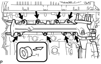
INSTALL STUD BOLT
Note
If a stud bolt is deformed or its threads are damaged, replace it.
-
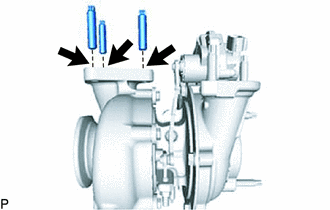
Using an E10 "TORX" socket wrench, install the 3 stud bolts at the positions shown in the illustration.
- Torque:
- 15 N*m { 150 kgf*cm, 11 ft.*lbf }
-
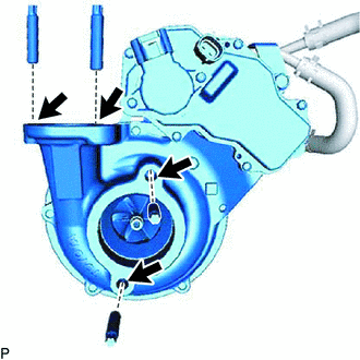
Using an E8 "TORX" socket wrench, install the 4 stud bolts at the positions shown in the illustration.
- Torque:
- 10 N*m { 102 kgf*cm, 7 ft.*lbf }
-
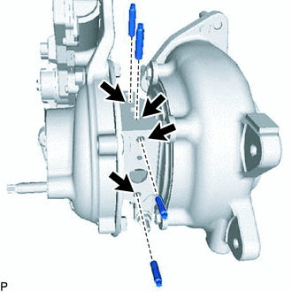
Using an E5 "TORX" socket wrench, install the 4 stud bolts at the positions shown in the illustration.
- Torque:
- 5.5 N*m { 56 kgf*cm, 49 in.*lbf }
-
-
INSTALL COMPRESSOR OUTLET ELBOW
-
Install the hose clamp with the bolt.
- Torque:
- 10 N*m { 102 kgf*cm, 7 ft.*lbf }
-
Install a new gasket.
-
Install a new gasket and the compressor outlet elbow with the 2 nuts.
- Torque:
- 21 N*m { 214 kgf*cm, 15 ft.*lbf }
-
-
INSTALL COMPRESSOR INLET ELBOW
-
Install a new gasket.
-
Using an E8 "TORX" socket wrench, install a new gasket and the compressor inlet elbow with the stud bolt.
- Torque:
- 10 N*m { 102 kgf*cm, 7 ft.*lbf }
-
Install the compressor inlet elbow to the turbocharger sub-assembly with the 2 nuts.
- Torque:
- 21 N*m { 214 kgf*cm, 15 ft.*lbf }
-
Install the compressor inlet elbow stay with the 2 bolts.
- Torque:
- 21 N*m { 214 kgf*cm, 15 ft.*lbf }
-
-
INSTALL NO. 1 TURBO WATER PIPE SUB-ASSEMBLY
-
Install a new gasket.
-
Temporarily install the turbo water pipe sub-assembly with the bolt and 2 nuts.
-
Tighten the bolt and 2 nuts.
- Torque:
- 13 N*m { 133 kgf*cm, 10 ft.*lbf }
-
Connect the No. 1 turbo water hose and No. 2 turbo water hose to the No. 1 turbo water pipe sub-assembly and slide the 2 hose clips to secure the hoses.
-
-
TEMPORARILY INSTALL TURBO OIL INLET PIPE SUB-ASSEMBLY
-
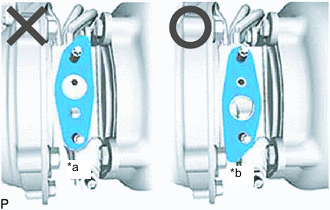
Text in Illustration *a NG *b OK Install a new gasket as shown in the illustration.
Note
Do not install the gasket upside down.
-
Temporarily install the turbo oil inlet pipe subassembly with the 2 nuts.
-
-
TEMPORARILY INSTALL EXHAUST MANIFOLD WITH TURBOCHARGER SUB-ASSEMBLY
-
Install 2 new gaskets to the exhaust manifold and turbocharger sub-assembly.
-
Temporarily install the exhaust manifold to turbocharger sub-assembly with 3 new nuts.
-
Text in Illustration *1 Collar 
Engine Side Temporarily install the exhaust manifold with turbocharger sub-assembly, 8 collars and the 8 plate washers to the cylinder head sub-assembly with 8 new nuts.
Note
Make sure that the side of the collar with the smaller diameter faces the exhaust manifold.
-
Install a new gasket on the union bolt side to turbo oil inlet pipe sub-assembly.
-
Temporarily install the union bolt.
-
-
INSTALL TURBO OIL OUTLET PIPE
-
Install a new gasket to the turbo oil outlet pipe.
Note
The claws of the gasket must face the turbo oil outlet pipe.
-
Install the turbo oil outlet pipe with the 2 bolts.
- Torque:
- 12 N*m { 122 kgf*cm, 9 ft.*lbf }
-
Connect the turbo oil outlet hose to the turbo oil outlet pipe, turbo oil inlet pipe and slide the 2 hose clips to secure the hoses.
-
-
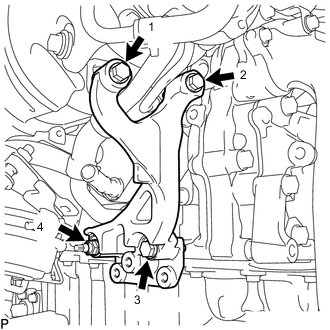
TEMPORARILY INSTALL TURBOCHARGER STAY
-
for Type B:
Temporarily install the turbocharger stay to the turbocharger sub-assembly, with 3 bolts and nut.
-
for Type A:
-
Temporarily install the turbocharger stay and stad bolt.
-
Using an E8 "TORX" socket wrench, tighten the stud bolt.
- Torque:
- 10 N*m { 102 kgf*cm, 7 ft.*lbf }
-
Temporarily install the 3 bolts and nut.
-
-
-
TIGHTEN EXHAUST MANIFOLD WITH TURBOCHARGER SUB-ASSEMBLY
-
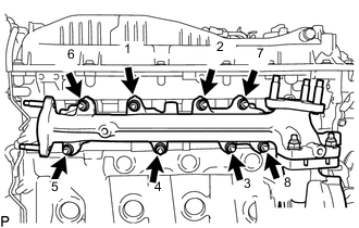
Tighten the exhaust manifold with turbocharger sub-assembly, to the cylinder head sub-assembly with 8 nuts.
- Torque:
- 40 N*m { 408 kgf*cm, 30 ft.*lbf }
Tech Tips
Tighten the nuts in the order shown in the illustration.
-
Tighten the turbocharger sub-assembly, to the exhaust manifold with the 3 nuts.
- Torque:
- 73 N*m { 744 kgf*cm, 54 ft.*lbf }
-
Tighten the 2 nuts and then union bolt of the turbo oil inlet pipe sub-assembly.
- Torque:
- for nut
- 13 N*m { 133 kgf*cm, 10 ft.*lbf }
- for union bolt
- 36 N*m { 367 kgf*cm, 27 ft.*lbf }
Note
If the connecting part of the union bolt gasket is cracked, remove the connecting part.
-
-
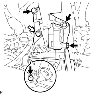
TIGHTEN TURBOCHARGER STAY
-
Tighten the 3 bolts and nut of the turbocharger stay in the order shown in the illustration.
- Torque:
- 24 N*m { 245 kgf*cm, 18 ft.*lbf }
-
-
INSTALL VISCOUS HEATER NO.1 BRACKET SUB-ASSEMBLY (for Cold Area Specification Vehicles)
Text in Illustration 
No. 1 Viscous Heater Bracket Bolt No. 4 Engine Harness Bolt
-
Temporarily install the No. 1 viscous heater bracket sub-assembly with 4 bolts.
-
Tighten the 4 bolts and of the No. 1 viscous heater bracket sub-assembly in the order shown in the illustration.
- Torque:
- 25 N*m { 250 kgf*cm, 18 ft.*lbf }
-
Connect the No. 4 engine harness with the bolt.
- Torque:
- 13 N*m { 133 kgf*cm, 10 ft.*lbf }
-
Connect the wire harness.
-
-
INSTALL OIL COOLER TUBE BRACKET AND WIRE HARNESS CLAMPBRACKET
-
Connect the wire harness clamp bracket with the bolt.
- Torque:
- 13 N*m { 130 kgf*cm, 9 ft.*lbf }
-
for Automatic Transmission:
Connect the oil cooler tube bracket with the bolt.
- Torque:
- 5.5 N*m { 56 kgf*cm, 47 in.*lbf }
-
-
INSTALL NO. 1 EGR PIPE SUB-ASSEMBLY
-
CONNECT TURBO WATER HOSE
-
Connect the No. 1 turbo water hose and No. 2 turbo water hose to the water outlet sub-assembly, engine water pump assembly and slide the 2 hose clips to secure the hoses.
Note
The turbocharger sub-assembly may be damaged if the No. 1 turbo water hose and No. 2 turbo water hose are connected to the wrong locations.
-
-
CONNECT NO. 1 WATER BY-PASS PIPE
-
INSTALL PCV HOSE (except Cold Area Specification Vehicles)
-
Attach the clamp and install the PCV hose.
-
Slide the 2 hose clips to secure the hoses.
-
-
INSTALL PCV PIPE (for Cold Area Specification Vehicles)
-
Connect the PCV pipe to the compressor inlet elbow, cylinder head cover sub-assembly and slide the 2 hose clips to secure the hoses.
-
Install the PCV pipe with the bolt to the compressor inlet elbow.
- Torque:
- 10 N*m { 102 kgf*cm, 7 ft.*lbf }
-
Connect the No. 19 water by-pass hose to the compressor inlet elbow and slide the hose clip to secure the hoses.
-
Install the No. 20 water by-pass hose to the PCV pipe and No. 1 water by-pass pipe, and slide the 2 hose clips to secure the hoses.
-
-
INSTALL NO. 3 WATER BY-PASS PIPE
-
Connect the 2 water hoses to the oil cooler assembly and No. 2 water by-pass pipe, and slide the 2 hose clips to secure the hoses.
-
Install the No. 3 water by-pass pipe with the bolt.
- Torque:
- 21 N*m { 214 kgf*cm, 15 ft.*lbf }
-
for Cold Area Specification Vehicles:
Install the water hose to the compressor inlet elbow and No. 3 water by-pass pipe, and slide the 2 hose clips to secure the hoses.
-
-
INSTALL WATER HOSE SUB-ASSEMBLY B (w/ Viscous Heater)
-
INSTALL VISCOUS WITH MAGNET CLUTCH HEATER ASSEMBLY
-
INSTALL AIR CLEANER CASE
-
Install the air cleaner case sub-assembly with the 3 bolts.
- Torque:
- 12 N*m { 122 kgf*cm, 9 ft.*lbf }
-
for Cold Area Specification Vehicles:
Connect the wire harness clamps.
-
-
INSTALL AIR CLEANER FILTER ELEMENT SUB-ASSEMBLY
-
Install the air cleaner filter element sub-assembly to the air cleaner case.
-
-
CONNECT AIR CLEANER CAP SUB-ASSEMBLY WITH AIR CLEANER HOSE
-
Attach the 4 clips to install the air cleaner cap sub-assembly with air cleaner hose.
-
Tighten the hose clamp.
- Torque:
- 5.0 N*m { 51 kgf*cm, 44 in.*lbf }
-
Connect the mass air flow meter connector and attach the 2 wire harness clamps.
-
-
INSTALL FAN SHROUD
-
INSTALL RADIATOR RESERVOIR ASSEMBLY
-
INSTALL NO. 1 RADIATOR HOSE
-
INSTALL VANE PUMP OIL RESERVOIR SUB-ASSEMBLY
-
INSTALL NO. 2 INTERCOOLER AIR HOSE
-
INSTALL INTERCOOLER AIR HOSE
-
INSTALL EXHAUST MANIFOLD CONVERTER SUB-ASSEMBLY
-
CONNECT CABLE TO NEGATIVE BATTERY TERMINAL
Note
When disconnecting the cable, some systems need to be initialized after the cable is reconnected Click here.
-
ADD ENGINE OIL
-
ADD ENGINE COOLANT
-
INSPECT FOR OIL LEAK
-
INSPECT ENGINE OIL LEVEL
-
INSPECT FOR COOLANT LEAK
-
INSPECT FOR EXHAUST GAS LEAK