EXHAUST MANIFOLD W/ TURBOCHARGER REMOVAL
PROCEDURE
-
DISCONNECT CABLE FROM NEGATIVE BATTERY TERMINAL
Note
When disconnecting the cable, some systems need to be initialized after the cable is reconnected (See page ).
-
REMOVE EXHAUST MANIFOLD CONVERTER SUB-ASSEMBLY
-
DRAIN ENGINE COOLANT
-
DRAIN ENGINE OIL
-
REMOVE INTERCOOLER AIR HOSE
-
REMOVE NO. 2 INTERCOOLER AIR HOSE
-
DISCONNECT VANE PUMP OIL RESERVOIR SUB-ASSEMBLY
-
REMOVE NO. 1 RADIATOR HOSE
-
REMOVE RADIATOR RESERVOIR ASSEMBLY
-
DISCONNECT NO. 3 ENGINE WIRE (for Cold Area Specification Vehicles)
-
REMOVE FAN SHROUD
-
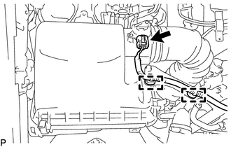
REMOVE AIR CLEANER CAP SUB-ASSEMBLY WITH AIR CLEANER HOSE
-
Disconnect the mass air flow meter sub-assembly connector and detach the 2 harness clamps.
-
Detach the 4 clips.
-
Loosen the hose clamp and remove the air cleaner cap sub-assembly with air cleaner hose.
-
-
REMOVE AIR CLEANER FILTER ELEMENT SUB-ASSEMBLY
-
Remove the air cleaner element sub-assembly from the air cleaner case.
-
-
REMOVE AIR CLEANER CASE SUB-ASSEMBLY
-
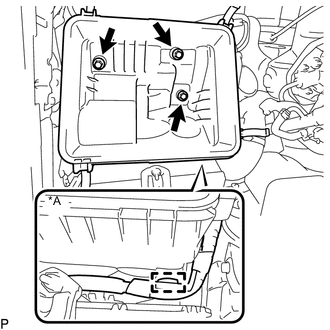
Text in Illustration *A for Cold Area Specification Vehicles Remove the 3 bolts and air cleaner case sub-assembly.
-
-
DISCONNECT VISCOUS WITH MAGNET CLUTCH HEATER ASSEMBLY (for Cold Area Specification Vehicles)
-
REMOVE WATER HOSE SUB-ASSEMBLY B (w/ Viscous Heater)
-
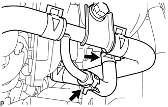
REMOVE NO. 3 WATER BY-PASS PIPE
-
for Cold Area Specification Vehicles:
Slide the 2 clips and remove the water hose from the compressor inlet elbow and No. 3 water by-pass pipe.
-
Text in Illustration *A for Cold Area Specification Vehicles *B except Cold Area Specification Vehicles Slide the 2 clips and disconnect the 2 water hoses from the oil cooler assembly and No. 2 water bypass pipe.
-
Remove the bolt and No. 3 water by-pass pipe.
-
-
REMOVE PCV PIPE (for Cold Area Specification Vehicles)
-
Slide the 2 clips and disconnect the No. 20 water by-pass hose from the compressor inlet elbow and No. 3 water by-pass pipe.
-
Slide the clip and disconnect the No. 19 water bypass hose from the compressor inlet elbow.
-
Remove the bolt and disconnect the PCV pipe from the compression inlet elbow.
-
Slide the 2 clips and remove the PCV pipe.
-
-
REMOVE PCV HOSE (except Cold Area Specification Vehicles)
-
Slide the 2 clips.
-
Slide the 2 clips, detach the clamp and remove the PCV hose.
-
-
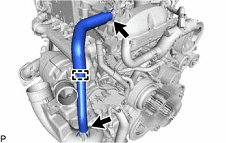
REMOVE NO. 1 WATER BY-PASS PIPE
-
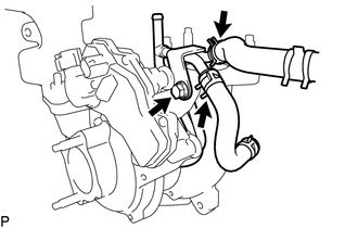
DISCONNECT TURBO WATER HOSE
-
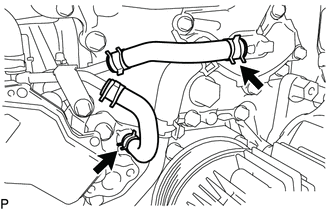
Slide the 2 clips and disconnect the No. 1 turbo water hose and No. 2 turbo water hose from the water outlet sub-assembly and water pump assembly.
-
-
REMOVE OIL COOLER TUBE BRACKET AND WIREHARNESS CLAMP BRACKET
-
for Automatic Transmission:
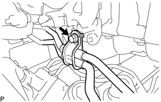
Remove the bolt and disconnect the oil cooler tube bracket.
-
Remove the bolt and disconnect the wire harness.
-
-
DISCONNECT NO. 1 VISCOUS HEATER BRACKET SUB-ASSEMBLY (for Cold Area Specification Vehicles)
-
Remove the detach the clamp and disconnect the wire harness.
-
Remove the bolt and disconnect the No. 4 engine harness.
Text in Illustration 
No. 1 Viscous Heater Bracket Sub-assembly Bolt 
No. 4 Engine Harness Bolt -
Remove the 4 bolts and No. 1 viscous heater bracket sub-assembly.
-
-
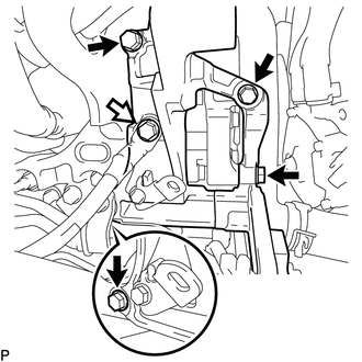
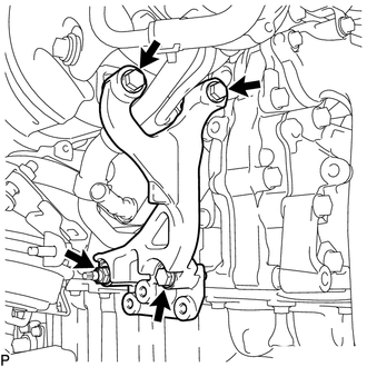
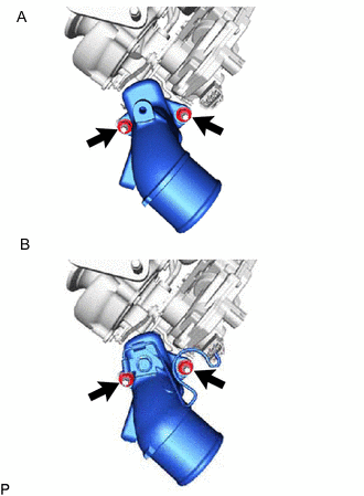
REMOVE TURBOCHARGER STAY
-
for Type A:
-
Remove the 3 bolts and nut.
-
Using an E8 "TORX" socket wrench, remove the stud bolt and turbocharger stay.
-
-
for Type B:
Remove the 3 bolts, nut and the turbocharger stay.
-
-
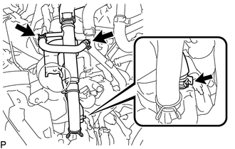
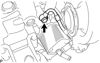
REMOVE TURBO OIL OUTLET PIPE
-
Slide the 2 clips and disconnect the turbo oil outlet hose from the turbo oil outlet pipe.
-
except Cold Area Specification Vehicles and w/ Cover
Remove the cover from the turbo oil outlet pipe.
-
Remove the 2 bolts and turbo oil outlet pipe and gasket.
-
-
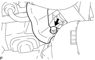
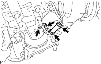
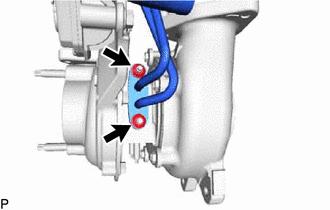
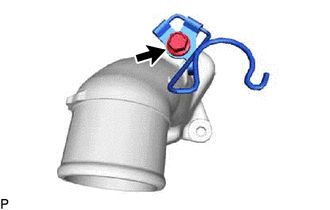
REMOVE TURBO OIL INLET PIPE SUB-ASSEMBLY
-
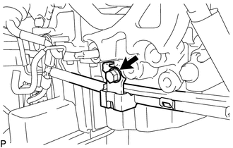
Remove the union bolt and gasket.
-
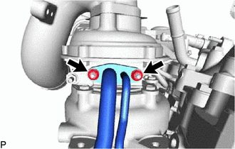
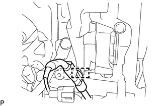
Remove the 2 nuts and the turbo oil inlet pipe subassembly.
Note
Do not loosen the nut labeled A.
-
Remove the gasket.
-
-
REMOVE TURBOCHARGER SUB-ASSEMBLY
-
Remove the 3 nuts and turbocharger sub-assembly.
-
Remove the gasket from the exhaust manifold.
-
-
REMOVE NO. 1 EGR PIPE SUB-ASSEMBLY
-
REMOVE EXHAUST MANIFOLD
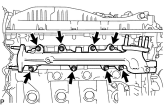
-
Remove the 8 nuts, 8 plate washers, 8 collars and exhaust manifold.
-
Remove the gasket.
-
-
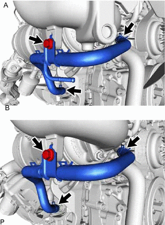
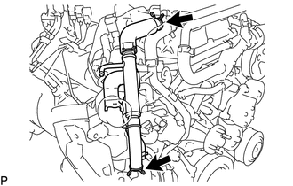
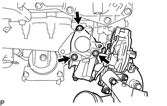
REMOVE NO. 1 TURBO WATER PIPE SUB-ASSEMBLY
-
Slide the 2 hose clips and disconnect the No. 1 turbo water hose and No. 2 turbo water hose from the turbo water pipe sub-assembly.
-
Remove the bolt.
-
Remove the 2 nuts, turbo water pipe sub-assembly and gasket.
-
-
REMOVE COMPRESSOR INLET ELBOW
-
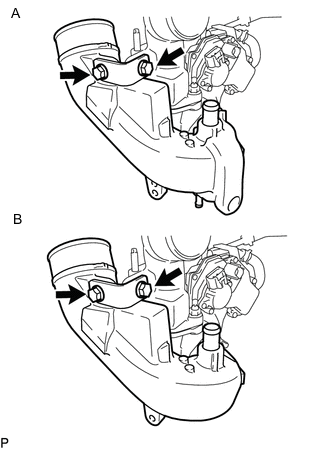
Text in Illustration *A for Cold Area Specification Vehicles *B except Cold Area Specification Vehicles Remove the 2 bolts and compressor inlet elbow stay.
-
Text in Illustration *A for Cold Area Specification Vehicles *B except Cold Area Specification Vehicles Remove the 2 nuts and compressor inlet elbow from turbocharger sub-assembly.
-
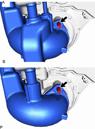
Text in Illustration *A for Cold Area Specification Vehicles *B except Cold Area Specification Vehicles Using an E8 "TORX" socket wrench, remove the stud bolt shown in the illustration together with the compressor inlet elbow and gasket.
-
-
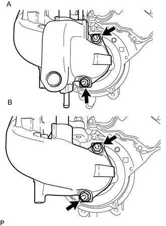
REMOVE COMPRESSOR OUTLET ELBOW
-
Text in Illustration *A for Cold Area Specification Vehicles *B except Cold Area Specification Vehicles Remove the 2 nuts and compressor outlet elbow.
-
Remove the gasket.
-
except Cold Area Specification Vehicles:
Remove the bolt and hose clamp
-
-
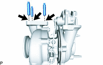
DISCONNECT STUD BOLT
-
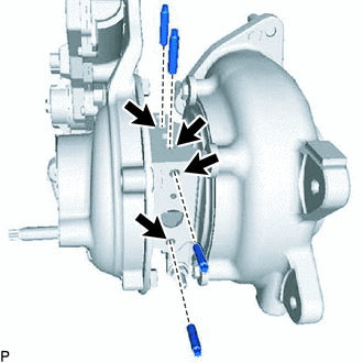
Using an E5 "TORX" socket wrench, remove the 4 stud bolts shown in the illustration.
Note
If a stud bolt is deformed or its threads are damaged, replace it.
-
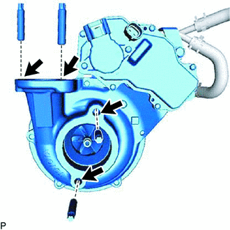
Using an E8 "TORX" socket wrench, remove the 4 stud bolts shown in the illustration.
-
Using an E10 "TORX" socket wrench, remove the 3 stud bolts shown in the illustration.
-