INTAKE MANIFOLD INSTALLATION
PROCEDURE
-
INSTALL INTAKE MANIFOLD
-
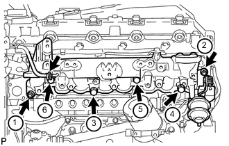
Temporarily install a new gasket and the intake manifold with the 2 nuts and 4 bolts.
-
Tighten the 2 nuts and 4 bolts in the order shown in the illustration.
- Torque:
- 29 N*m { 296 kgf*cm, 21 ft.*lbf }
Note
-
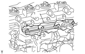
When installing the intake manifold, make sure that the No. 1 intake manifold insulator is not pinched.
-
Make sure that the swirl control valve actuator is not damaged by the surrounding parts.
Text in Illustration *1 No. 1 Intake Manifold Insulator
-
Connect the vacuum hose to the intake manifold.
-
Attach the sensor wire connector clamp to the intake manifold.
-
-
INSTALL INTAKE MANIFOLD INSULATOR
-
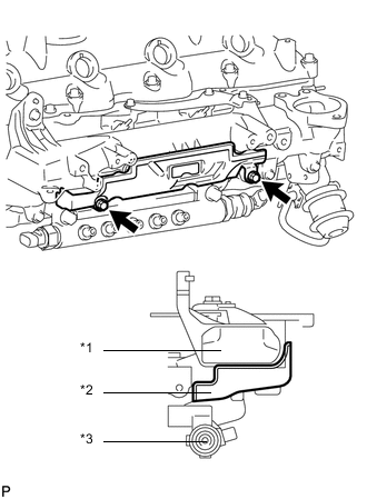
Text in Illustration *1 Intake Manifold *2 Intake Manifold Insulator *3 Common Rail Install the intake manifold insulator with the 2 bolts.
- Torque:
- 8.0 N*m { 82 kgf*cm, 71 in.*lbf }
-
-
INSTALL NO. 2 NOZZLE LEAKAGE PIPE ASSEMBLY
-
INSTALL NO. 4 INJECTION PIPE SUB-ASSEMBLY
-
INSTALL VACUUM CONTROL VALVE SET
-
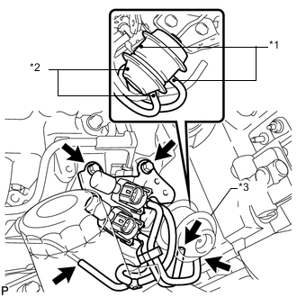
Text in Illustration *1 Paint Mark (White) *2 Paint Mark (Green) *3 Swirl Control Valve Actuator Install the vacuum control valve set with the 2 bolts.
- Torque:
- 20 N*m { 204 kgf*cm, 15 ft.*lbf }
-
Connect the 3 vacuum hoses and 2 VSV connectors.
Note
When connecting the hoses, match the colors of the paint marks on the hoses to the colors of the paint marks on the swirl control valve as shown in the illustration.
-
-
INSTALL INTAKE PIPE OR HOSE STAY
-
Install the intake pipe stay with the bolt.
- Torque:
- 23 N*m { 235 kgf*cm, 17 ft.*lbf }
-
-
INSTALL MANIFOLD STAY WITH VACUUM SWITCHING VALVE
-
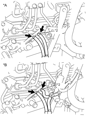
Text in Illustration *A w/o EGR System *B w/ EGR System *1 White Mark *2 Blue Mark Install the manifold stay with vacuum switching valve with the 2 bolts and connect the No. 3 vacuum transmitting hose and No. 4 vacuum transmitting hose.
- Torque:
- 19 N*m { 194 kgf*cm, 14 ft.*lbf }
Note
Make sure the vacuum hose color matches the connection area color.
-
w/ EGR Cooler:
Connect the No. 3 vacuum transmitting hose.
-
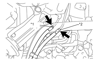
Text in Illustration *1 Yellow Mark *2 Pink Mark w/ EGR System:
Connect the No. 2 vacuum transmitting hose and No. 3 vacuum transmitting hose.
Note
-
Make sure the vacuum hose color matches the connection area color.
-
Push on the hose until it reaches the bent part of the pipe.
-
-
Connect the No. 1 vacuum transmitting hose.
-
Connect the vacuum switching valve connector.
-
w/o EGR System:
Connect the connector.
-
w/ EGR System without EGR Cooler:
Connect the 2 connectors.
-
w/ EGR System with EGR Cooler:
Connect the 3 connectors.
-
-
-
INSTALL INTAKE AIR CONNECTOR WITH DIESEL THROTTLE BODY ASSEMBLY (w/o EGR System)
-
CONNECT ENGINE WIRE (w/o EGR System)
-
INSTALL AIR CONNECTOR STAY (w/o EGR System)
-
INSTALL NO. 1, NO. 2 AND NO. 3 INJECTION PIPE SUB-ASSEMBLY (w/o EGR System)
-
INSTALL THROTTLE BODY BRACKET (w/o EGR System)
-
INSTALL NO. 1 INTAKE PIPE (w/o EGR System)
-
CONNECT NO. 4 VACUUM TRANSMITTING PIPE SUB-ASSEMBLY (w/o EGR System)
-
CONNECT INLET HEATER WATER HOSE (w/o EGR System)
-
INSTALL ELECTRIC EGR CONTROL VALVE ASSEMBLY (w/ EGR System)
-
Install the electric EGR control valve assembly Click here.
-
-
CONNECT CABLE TO NEGATIVE BATTERY TERMINAL
Note
When disconnecting the cable, some systems need to be initialized after the cable is reconnected Click here.
-
ADD ENGINE COOLANT (w/ EGR System with EGR Cooler)
-
BLEED AIR FROM FUEL SYSTEM
-
INSPECT FOR COOLANT LEAK (w/ EGR System with EGR Cooler)
-
INSPECT FOR FUEL LEAK