EMISSION CONTROL SYSTEM SYSTEM DIAGRAM
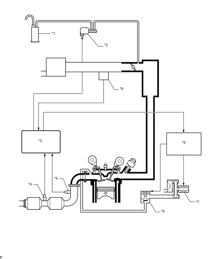
| *1 | Canister | *2 | Purge VSV |
| *3 | ECM | *4 | Heated Oxygen Sensor |
| *5 | Air Fuel Ratio Sensor | *6 | Air Injection Control Driver |
| *7 | Air Pump | *8 | Air Switching Valve |
| *9 | Air Pressure Sensor | - | - |
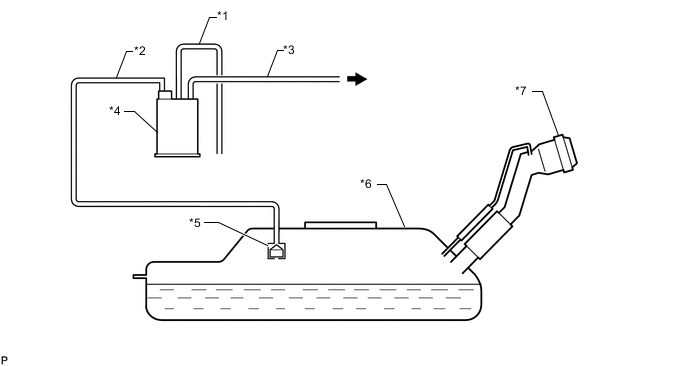
| *1 | Air Inlet Line | *2 | Vent Line |
| *3 | Purge Line | *4 | Canister |
| *5 | Fuel Cutoff Valve | *6 | Fuel Tank |
| *7 | Fuel Tank Cap | - | - |
 |
to Purge VSV | - | - |
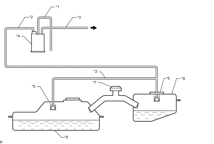
| *1 | Air Inlet Line | *2 | Vent Line |
| *3 | Purge Line | *4 | Canister |
| *5 | Fuel Cutoff Valve | *6 | Fuel Tank |
| *7 | Fuel Tank Cap | *8 | Fuel Sub Tank |
| |
to Purge VSV | - | - |