EXHAUST MANIFOLD W/ TURBOCHARGER INSTALLATION
PROCEDURE
-
INSTALL NO. 1 TURBO WATER PIPE SUB-ASSEMBLY
-
Install a new gasket and the No. 1 turbo water pipe sub-assembly and bolt to the turbocharger sub-assembly with the 2 nuts.
- Torque:
- for bolt
- 8.0 N*m { 82 kgf*cm, 71 in.*lbf }
- for nut
- 12 N*m { 122 kgf*cm, 9 ft.*lbf }
-
-
INSTALL EXHAUST MANIFOLD WITH TURBOCHARGER SUB-ASSEMBLY
-
Temporarily install a new gasket and the turbocharger sub-assembly to the exhaust manifold with 3 new nuts.
Tech Tips
It is easier to install the turbo oil inlet pipe sub-assembly if the 3 nuts are only loosely installed.
-
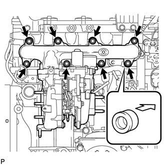
Set a new gasket on the engine and install the exhaust manifold with turbocharger sub-assembly, the 8 collars and the 8 plate washers with 8 new nuts.
- Torque:
- 40 N*m { 408 kgf*cm, 30 ft.*lbf }
Note
Install the collars so that the side with the smaller external diameter faces the exhaust manifold.
-
Temporarily install the turbo oil inlet pipe sub-assembly to the turbocharger sub-assembly.
Tech Tips
Before installing the turbo oil inlet pipe sub-assembly, clean it.
-
Install a new gasket and the turbo oil inlet pipe sub-assembly with the 2 nuts, but only loosely install the nuts.
Note
The notch (narrow part) of the gasket must face the engine.
-
Install a new gasket and the turbo oil inlet pipe sub-assembly with the 2 bolts, but only loosely install the bolts.
Note
The claws of the gasket must face the pipe.
-
Install a new gasket and the turbo oil inlet pipe sub-assembly with the union bolt, but only loosely install the union bolt.
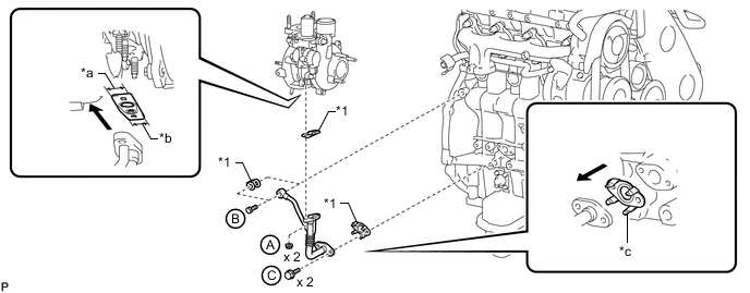
Text in Illustration *1 Gasket - - *a Wide *b Narrow *c Claw - - 
Outside - - -
Temporarily install the turbocharger stay to the turbocharger sub-assembly and cylinder block sub-assembly with the 2 bolts and nut.
-
-
Tighten the 3 nuts of the turbocharger sub-assembly.
- Torque:
- 52 N*m { 530 kgf*cm, 38 ft.*lbf }
-
Tighten the 2 nuts labeled A.
- Torque:
- 13 N*m { 133 kgf*cm, 10 ft.*lbf }
-
Tighten the union bolt labeled B.
- Torque:
- 33 N*m { 337 kgf*cm, 24 ft.*lbf }
-
Tighten the 2 bolts labeled C.
- Torque:
- 12 N*m { 122 kgf*cm, 9 ft.*lbf }
-
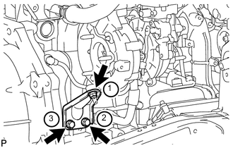
Tighten the 2 bolts and nut of the turbocharger stay in the order shown in the illustration.
- Torque:
- 38 N*m { 387 kgf*cm, 28 ft.*lbf }
-
-
INSTALL TURBINE OUTLET ELBOW
-
Install a new gasket and the turbine outlet elbow to the turbocharger sub-assembly with the 3 nuts.
- Torque:
- 39 N*m { 398 kgf*cm, 29 ft.*lbf }
-
-
CONNECT NO. 1 TURBO WATER HOSE
-
Connect the No. 1 turbo water hose to the No. 1 turbo water pipe sub-assembly, and slide the clamp to secure the hose.
-
-
INSTALL NO. 1 EXHAUST MANIFOLD HEAT INSULATOR
-
Temporarily install the No. 1 exhaust manifold heat insulator to the exhaust manifold with the bolt.
-
-
INSTALL NO. 1 TURBO INSULATOR
-
Temporarily install the No. 1 turbo insulator to the turbocharger sub-assembly with the 2 bolts.
-
Tighten the bolt of the No. 1 exhaust manifold heat insulator and the 2 bolts of the No. 1 turbo insulator.
- Torque:
- 12 N*m { 122 kgf*cm, 9 ft.*lbf }
-
-
INSTALL COMPRESSOR INLET ELBOW
-
Install a new gasket and the compressor inlet elbow with the 2 nuts.
- Torque:
- 19 N*m { 194 kgf*cm, 14 ft.*lbf }
-
Connect the No. 2 turbo water hose and No. 3 turbo water hose to the No. 1 turbo water pipe sub-assembly, and slide the clamp to secure the hose.
-
Connect the No. 3 turbo water hose and No. 3 turbo water hose to the No. 2 water by-pass pipe, and slide the clamp to secure the hose.
-
Connect the 2 connectors and attach the wire harness clamp.
-
Install the wire harness bracket to the water inlet with the bolt.
- Torque:
- 8.0 N*m { 82 kgf*cm, 71 in.*lbf }
-
Attach the 3 wire harness clamps.
-
-
INSTALL ENGINE OIL LEVEL DIPSTICK GUIDE
-
Install a new O-ring to the engine oil level dipstick guide.
-
Apply a small amount of clean engine oil to the O-ring.
-
Install the engine oil level dipstick guide to the cylinder block sub-assembly with the 2 bolts.
- Torque:
- 8.0 N*m { 82 kgf*cm, 71 in.*lbf }
-
Install the engine oil level dipstick.
-
-
INSTALL VENTILATION PIPE
-
Connect the 2 ventilation hoses and install the ventilation pipe to the cylinder head cover to the cylinder head sub-assembly with the bolt.
- Torque:
- 18 N*m { 184 kgf*cm, 13 ft.*lbf }
-
Type A
Connect the No. 3 turbo water hose and No. 4 turbo water hose to the ventilation pipe, and slide the 2 clamps to secure the hose.
-
-
INSTALL NO. 1 COMPRESSOR MOUNTING BRACKET
-
INSTALL GENERATOR BRACKET
-
INSTALL GENERATOR ASSEMBLY
-
CONNECT COOLER COMPRESSOR ASSEMBLY (w/ Air Conditioning System)
-
INSTALL NO. 1 VISCOUS HEATER BRACKET SUB-ASSEMBLY (for Cold Area Specification Vehicles)
-
INSTALL VISCOUS WITH MAGNET CLUTCH HEATER ASSEMBLY (for Cold Area Specification Vehicles)
-
INSTALL COMPRESSOR OUTLET ELBOW
-
Install the compressor outlet elbow with the 2 bolts and tighten the hose clamp.
- Torque:
- for bolt
- 20 N*m { 204 kgf*cm, 15 ft.*lbf }
- for hose clamp
- 6.5 N*m { 66 kgf*cm, 58 in.*lbf }
-
Install the wire harness bracket with the bolt.
- Torque:
- 8.0 N*m { 82 kgf*cm, 71 in.*lbf }
-
Attach the 3 wire harness clamps.
-
-
INSTALL NO. 1 AIR HOSE
-
INSTALL AIR CLEANER CASE SUB-ASSEMBLY
-
Install the air cleaner case sub-assembly with the 3 bolts.
- Torque:
- 12 N*m { 122 kgf*cm, 9 ft.*lbf }
-
-
INSTALL AIR CLEANER FILTER ELEMENT SUB-ASSEMBLY
-
INSTALL AIR CLEANER CAP SUB-ASSEMBLY
-
Attach the 4 clamps to install the air cleaner cap sub-assembly.
-
except Cold Area Specification Vehicles:
Attach the 2 clamps and connect the mass air flow meter connector.
-
for Cold Area Specification Vehicles:
Attach the 3 clamps and connect the mass air flow meter connector.
-
-
INSTALL NO. 1 AIR CLEANER HOSE
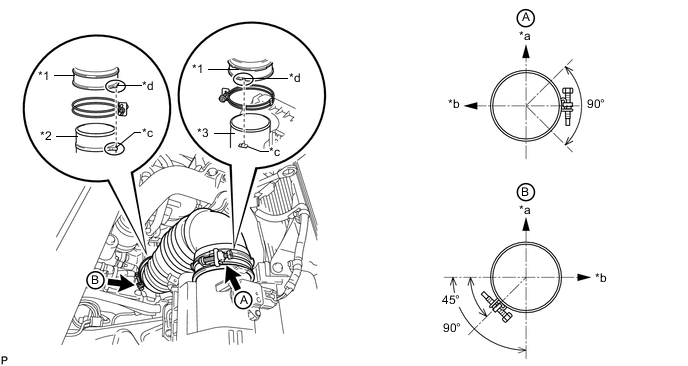
Text in Illustration *1 No. 1 Air Cleaner Hose *2 Compressor Inlet Elbow *3 Air Cleaner Cap - - *a Upper Side *b Front Side of Vehicle *c Protrusion *d Groove
-
Install the No. 1 air cleaner hose with the 2 hose clamps.
Note
-
When installing the No. 1 air cleaner hose, align the protrusion of the No. 1 air cleaner hose with the protrusion of the compressor inlet elbow as shown in the illustration.
-
When installing the No. 1 air cleaner hose, align the groove of the No. 1 air cleaner hose with the protrusion of the air cleaner cap as shown in the illustration.
-
-
Tighten the 2 hose clamps.
- Torque:
- 5.0 N*m { 51 kgf*cm, 44 in.*lbf }
Note
When tightening the 2 hose clamps, make sure that they are positioned as shown in the illustration.
-
-
INSTALL FAN AND GENERATOR V BELT
-
INSTALL FRONT HEATER BRACKET (for Cold Area Specification Vehicles)
-
INSTALL UPPER RADIATOR SUPPORT SEAL
-
INSTALL FRONT NO. 1 FENDER APRON TO FRAME SEAL RH
-
Install the front No. 1 fender apron to frame seal RH with the 5 clips.
-
-
INSTALL FRONT FENDER APRON SEAL RH
-
Install the front fender apron seal RH with the 4 clips.
-
-
INSTALL FRONT EXHAUST PIPE ASSEMBLY
-
CONNECT CABLE TO NEGATIVE BATTERY TERMINAL
Note
When disconnecting the cable, some systems need to be initialized after the cable is reconnected Click here.
-
ADD ENGINE COOLANT
-
INSPECT FOR COOLANT LEAK
-
INSPECT FOR OIL LEAK
-
INSPECT FOR EXHAUST GAS LEAK
-
INSTALL NO. 1 ENGINE UNDER COVER SUB-ASSEMBLY
-
INSTALL FRONT BUMPER LOWER COVER