UREA PUMP CONTROL ECU INSTALLATION
PROCEDURE
-
INSTALL UREA PUMP CONTROL ECU
-
Install the urea pump control ECU to the No. 1 urea pump control bracket with the 3 bolts.
- Torque:
- 3.0 N*m { 31 kgf*cm, 27 in.*lbf }
-
Temporarily install the No. 1 urea pump control bracket to the frame LH with the 3 bolts.
-
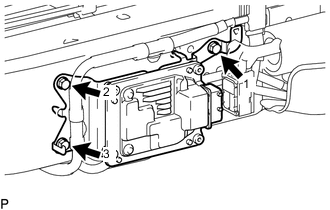
Tighten the 3 bolts in the order shown in the illustration.
- Torque:
- 31 N*m { 316 kgf*cm, 23 ft.*lbf }
-
Install the No. 4 urea pump control bracket to the urea pump control ECU.
- Torque:
- 3.0 N*m { 31 kgf*cm, 27 in.*lbf }
-
Attach the 3 clamps and connect the wire harness to the No. 4 urea pump control bracket and No. 1 urea pump control bracket.
-
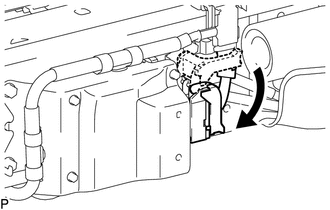
Connect the connector to the urea pump control ECU.
Note
When connecting a connector, make sure that dirt, water and other foreign matter is not stuck between the connector and urea pump control ECU.
-
-
INSTALL NO. 3 UREA PUMP CONTROL BRACKET
-
Install the No. 3 urea pump control bracket to the No. 4 urea pump control bracket with the bolt.
- Torque:
- 31 N*m { 316 kgf*cm, 23 ft.*lbf }
-
-
INSTALL NO. 2 UREA PUMP CONTROL BRACKET
-
Install the No. 2 urea pump control bracket to the frame LH with the 3 bolts.
- Torque:
- 31 N*m { 316 kgf*cm, 23 ft.*lbf }
-