EGR VALVE INSTALLATION
CAUTION / NOTICE / HINT
Note
-
When replacing the injectors (including shuffling the injectors between the cylinders), common rail or cylinder head, it is necessary to replace the injection pipes with new ones.
-
When replacing the fuel supply pump, common rail, cylinder block, cylinder head, cylinder head gasket or timing gear case, it is necessary to replace the fuel inlet pipe with a new one.
PROCEDURE
-
INSTALL NO. 2 EGR VALVE ASSEMBLY (w/ EGR Cooler)
-
Using a 6 mm hexagon wrench, install the EGR valve adapter, No. 2 EGR valve, EGR cooler, 2 new gaskets, 3 plate washers with the 3 hexagon bolts.
- Torque:
- 28 N*m { 286 kgf*cm, 21 ft.*lbf }
-
Using a 5 mm hexagon wrench, install the bolt labeled A.
- Torque:
- 13 N*m { 133 kgf*cm, 10 ft.*lbf }
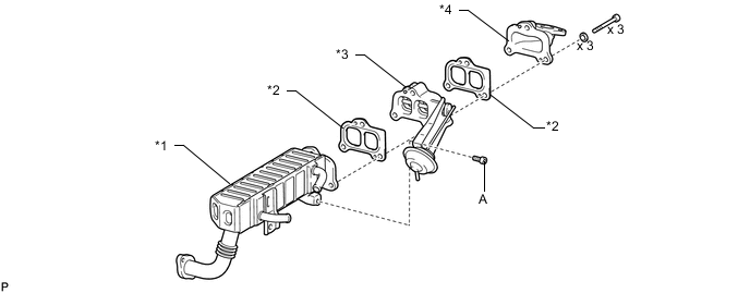
Text in Illustration *1 EGR Cooler with Pipe *2 New Gasket *3 No. 2 EGR Valve *4 EGR Valve Adapter
-
-
INSTALL EGR COOLER WITH PIPE (w/ EGR Cooler)
-
Install a new gasket and the EGR cooler with pipe to the electric EGR control valve and No. 2 EGR valve with the 2 bolts.
- Torque:
- 13 N*m { 133 kgf*cm, 10 ft.*lbf }
Tech Tips
Make sure the claws of the gasket face the electric EGR control valve.
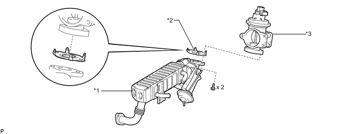
Text in Illustration *1 EGR Cooler with Pipe and No. 2 EGR Valve *2 New Gasket *3 Electric EGR Control Valve - -
-
-
TEMPORARILY INSTALL ELECTRIC EGR CONTROL VALVE ASSEMBLY (w/ EGR Cooler)
-
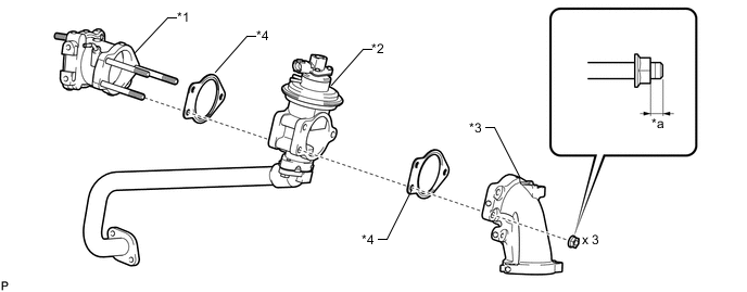
Place a new gasket, the electric EGR control valve, another new gasket and the intake air connector onto the stud bolts of the No. 2 intake air connector and temporarily install the 3 nuts.
Note
Temporarily install the nuts so that 0 to 2 threads of each stud bolt are visible as shown in the illustration.
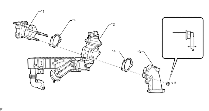
Text in Illustration *1 No. 2 Intake Air Connector *2 Electric EGR Control Valve *3 Intake Air Connector *4 New Gasket *a 0 to 2 threads - - -
Set a new gasket on the intake manifold.
Tech Tips
Make sure the claws of the gasket face the intake manifold.
-
Temporarily install the intake air connector to the intake manifold with the 3 bolts in the illustration.
-
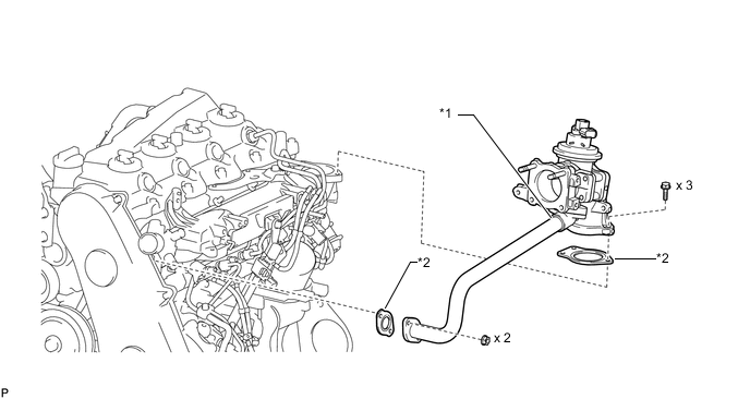
Temporarily install the EGR cooler with pipe and new gasket to the cylinder head with the bolt and 2 nuts.
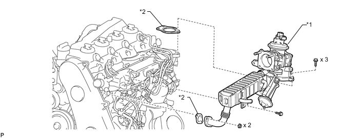
Text in Illustration *1 Electric EGR Control Valve *2 New Gasket -
Connect the No. 2 vacuum transmitting hose to the No. 2 EGR valve.
-
-
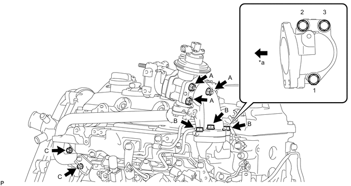
TIGHTEN ELECTRIC EGR CONTROL VALVE ASSEMBLY (w/ EGR Cooler)
-
Tighten the 3 nuts labeled A in the illustration.
- Torque:
- 20 N*m { 204 kgf*cm, 15 ft.*lbf }
-
Tighten the 3 bolts labeled B in the illustration.
- Torque:
- 20 N*m { 204 kgf*cm, 15 ft.*lbf }
Note
Tighten the bolts in the order shown in the illustration.
-
Tighten the bolt labeled C in the illustration.
- Torque:
- 22 N*m { 224 kgf*cm, 16 ft.*lbf }
-
Tighten the 2 nuts labeled D in the illustration.
- Torque:
- 13 N*m { 133 kgf*cm, 10 ft.*lbf }
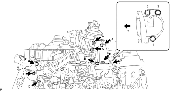
Text in Illustration *a Front - -
-
-
INSTALL NO. 1 EGR PIPE SUB-ASSEMBLY (w/o EGR Cooler)
-
Install a new gasket and the No. 1 EGR pipe to the electric EGR control valve with the 2 bolts.
- Torque:
- 13 N*m { 133 kgf*cm, 10 ft.*lbf }
Tech Tips
Make sure the claws of the gasket face the electric EGR control valve.
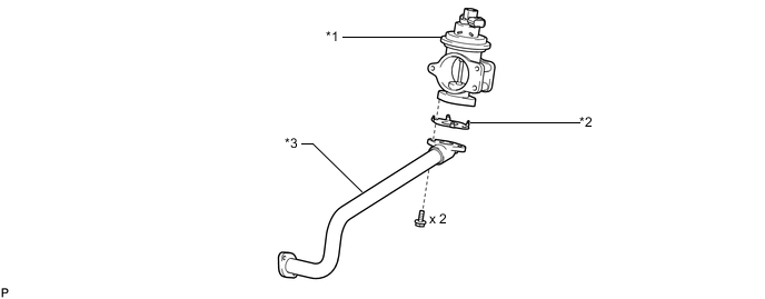
Text in Illustration *1 Electric EGR Control Valve *2 New Gasket *3 No. 1 EGR Pipe - -
-
-
TEMPORARILY INSTALL ELECTRIC EGR CONTROL VALVE ASSEMBLY (w/o EGR Cooler)
-
Place a new gasket, the electric EGR control valve, another new gasket and the intake air connector onto the stud bolts of the No. 2 intake air connector and temporarily install the 3 nuts.
Note
Temporarily install the nuts so that 0 to 2 threads of each stud bolt are visible as shown in the illustration.
Text in Illustration *1 No. 2 Intake Air Connector *2 Electric EGR Control Valve *3 Intake Air Connector *4 New Gasket *a 0 to 2 threads - - -
Set a new gasket on the intake manifold.
Tech Tips
Make sure the claws of the gasket face the intake manifold.
-
Temporarily install the intake air connector to the intake manifold with the 3 bolts.
-
Temporarily install the No. 1 EGR pipe and a new gasket to the cylinder head with the 2 nuts.
Text in Illustration *1 Electric EGR Control Valve *2 New Gasket
-
-
TIGHTEN ELECTRIC EGR CONTROL VALVE ASSEMBLY (w/o EGR Cooler)
-
Tighten the 3 nuts labeled A in the illustration.
- Torque:
- 20 N*m { 204 kgf*cm, 15 ft.*lbf }
-
Tighten the 3 bolts labeled B in the illustration.
- Torque:
- 20 N*m { 204 kgf*cm, 15 ft.*lbf }
Note
Tighten the bolts in the order shown in the illustration.
-
Tighten the 2 nuts labeled C in the illustration.
- Torque:
- 13 N*m { 133 kgf*cm, 10 ft.*lbf }
Text in Illustration *a Front - -
-
-
INSTALL AIR CONNECTOR STAY
-
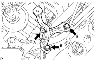
Temporarily install the air connector stay with the 3 bolts.
-
Tighten the bolt labeled A.
- Torque:
- 20 N*m { 204 kgf*cm, 15 ft.*lbf }
-
Tighten the 2 bolts labeled B.
- Torque:
- 20 N*m { 204 kgf*cm, 15 ft.*lbf }
-
-
INSTALL ELECTRIC VACUUM REGULATING VALVE ASSEMBLY
-
Install the E-VRV bracket with the 2 bolts.
- Torque:
- 20 N*m { 204 kgf*cm, 15 ft.*lbf }
-
Install the gas filter and the gas filter bracket with the bolt.
- Torque:
- 20 N*m { 204 kgf*cm, 15 ft.*lbf }
-
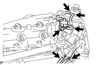
Text in Illustration *1 Yellow Mark *2 Pink Mark Connect the 5 vacuum hoses.
Note
Install the vacuum hoses so that they completely cover the pipes.
-
Connect the 2 connectors to the electric EGR control valve and E-VRV.
-
Attach the wire harness clamp.
-
-
INSTALL EGR VALVE BRACKET
-
Install the EGR valve bracket with the 2 nuts.
- Torque:
- 8.0 N*m { 82 kgf*cm, 71 in.*lbf }
-
-
CONNECT ENGINE WIRE (for LHD)
-
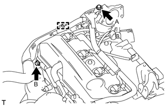
Attach the clamp.
-
Connect the engine wire with the 2 bolts.
- Torque:
- for bolt A
- 13 N*m { 131 kgf*cm, 9 ft.*lbf }
- for bolt B
- 22 N*m { 220 kgf*cm, 16 ft.*lbf }
-
-
CONNECT ENGINE WIRE (for RHD)
-
Connect the engine wire with the bolt.
- Torque:
- 13 N*m { 131 kgf*cm, 9 ft.*lbf }
-
-
INSTALL INJECTION PIPE
Note
-
When replacing an injector, it is necessary to replace the 4 injection pipes with new ones.
-
Keep the joints of the injection pipe clean.
-
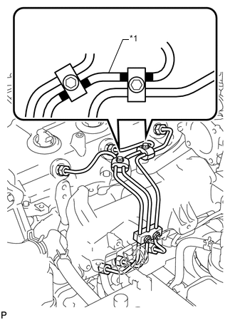
Text in Illustration *1 No. 2 Injection Pipe Temporarily install the No. 1, No. 2 and No. 3 injection pipes with the union nuts.
-
Install the No. 2 and No. 3 injection pipe clamps with the 2 bolts and 2 nuts as shown in the illustration.
- Torque:
- 5.0 N*m { 51 kgf*cm, 44 in.*lbf }
Tech Tips
If the painted mark on the No. 2 injection pipe has disappeared, use the illustration as a reference to install the clamps.
-
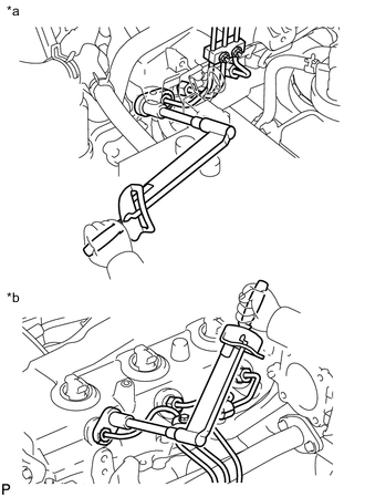
*a for Common Rail Side *b for Injector Side Using a 17 mm union nut wrench, tighten the injection pipe union nuts on the common rail side.
- Torque:
- 35 N*m { 357 kgf*cm, 26 ft.*lbf }
Note
Use the formula to calculate special torque values for situations where a union nut wrench is combined with a torque wrench Click here.
-
Using a 17 mm union nut wrench, tighten the injection pipe union nuts on the injector side.
- Torque:
- 35 N*m { 357 kgf*cm, 26 ft.*lbf }
Note
Use the formula to calculate special torque values for situations where a union nut wrench is combined with a torque wrench Click here.
-
-
CONNECT NO. 4 WATER BY-PASS HOSE (w/ EGR Cooler)
-
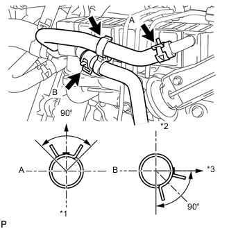
Text in Illustration *1 Lower Side *2 Upper Side *3 LH Side of Vehicle Connect the No. 4 water by-pass hose to the EGR cooler.
Tech Tips
-
The direction of the hose clamp is indicated in the illustration.
-
Insert the outlet hose into the stopper.
-
-
-
CONNECT NO. 3 WATER BY-PASS HOSE (w/ EGR Cooler)
-
Connect the No. 3 water by-pass hose to the EGR cooler.
Tech Tips
-
The direction of the hose clamp is indicated in the illustration.
-
Insert the outlet hose into the stopper.
-
-
Install the clamp.
-
-
INSTALL DIESEL THROTTLE BODY ASSEMBLY
-
Install the diesel throttle body Click here.
-
-
INSTALL COWL TOP VENTILATOR LOUVER SUB-ASSEMBLY
-
Install the cowl top ventilator louver Click here.
-
-
CONNECT CABLE TO NEGATIVE BATTERY TERMINAL
Note
When disconnecting the cable, some systems need to be initialized after the cable is reconnected Click here.
-
ADD ENGINE COOLANT (w/ EGR Cooler)
-
INSPECT FOR COOLANT LEAK (w/ EGR Cooler)
-
BLEED AIR FROM FUEL SYSTEM
-
INSPECT FOR FUEL LEAK
-
INSTALL NO. 1 ENGINE UNDER COVER SUB-ASSEMBLY
-
INSTALL FRONT BUMPER LOWER COVER