EGR VALVE REMOVAL
PROCEDURE
-
DRAIN ENGINE COOLANT
-
REMOVE DIESEL THROTTLE BODY ASSEMBLY
-
REMOVE WATER HOSE SUB-ASSEMBLY
-
w/ Rear Air Conditioning System:
-
Slide the 2 clamps and disconnect the 2 water hoses from the water pipe.
-
Slide the 2 clamps and disconnect the 2 water hoses from the air conditioning unit assembly.
-
Slide the 2 clamps and disconnect the 2 water hoses from the No. 2 water by-pass pipe.
-
-
w/o Rear Air Conditioning System:
-
Slide the 2 clamps and disconnect the 2 water hoses from the air conditioning unit assembly.
-
Slide the 2 clamps and disconnect the 2 water hoses from the No. 2 water by-pass pipe.
-
-
-
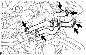
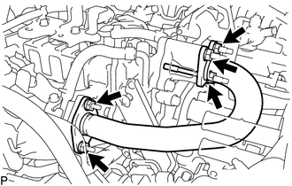
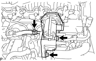
REMOVE NO. 2 WATER BY-PASS PIPE
-

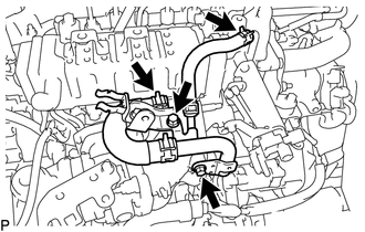
Slide the clamp and disconnect the No. 13 water by-pass hose from the water outlet sub-assembly.
-
Slide the clamp and disconnect the No. 15 water by-pass hose from the water by-pass pipe.
-
Slide the clamp and disconnect the No. 16 water by-pass hose from the No. 1 EGR cooler.
-
Remove the 3 bolts and No. 2 water by-pass pipe from the cylinder head cover sub-assembly, No. 3 water by-pass pipe sub-assembly and No. 2 engine cover bracket.
-
-
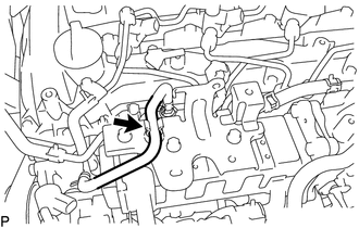
REMOVE GAS FILTER
-
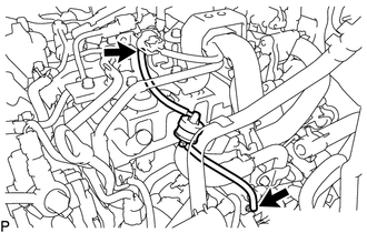
Disconnect the 2 vacuum hoses from the turbo pressure sensor and intake manifold.
-
Remove the gas filter from the gas filter bracket.
-
-
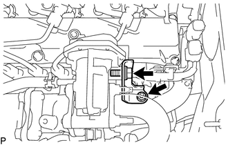
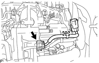
REMOVE DIESEL TURBO PRESSURE SENSOR
-
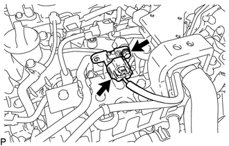
Disconnect the connector from the turbo pressure sensor.
-
Remove the bolt and turbo pressure sensor from the No. 3 water by-pass pipe sub-assembly.
-
-
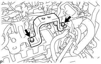
REMOVE NO. 3 ENGINE COVER BRACKET
-
Remove the 2 bolts and No. 3 engine cover bracket from the engine cover bracket and No. 2 engine cover bracket.
-
-
REMOVE NO. 2 ENGINE COVER BRACKET
-
Remove the 2 bolts and No. 2 engine cover bracket from the No. 3 water by-pass pipe sub-assembly and No. 2 EGR valve assembly.
-
-
DISCONNECT UREA TANK FILLER PIPE ASSEMBLY (w/ Urea SCR System)
-
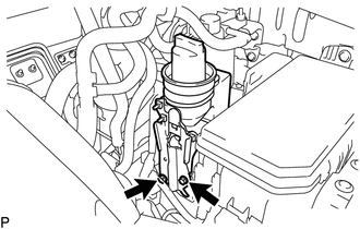
Remove the 2 bolts and disconnect the urea tank filler pipe assembly from the No. 1 oil reservoir bracket assembly.
-
-
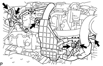
DISCONNECT VANE PUMP OIL RESERVOIR SUB-ASSEMBLY
-
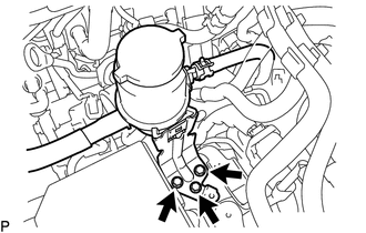
Remove the 3 bolts and disconnect the vane pump oil reservoir sub-assembly from the body.
-
-
DISCONNECT ENGINE WIRE
-
Detach the 2 clamps and disconnect the 2 connectors from the turbocharger sub-assembly.
-
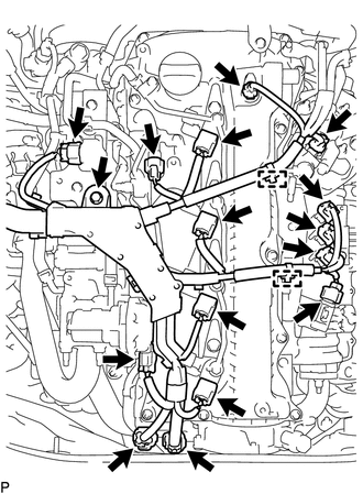
Detach the clamp and disconnect the connector from the differential pressure sensor.
-
Disconnect the 3 connectors from the exhaust gas temperature sensors.
-
Disconnect the connector from the exhaust fuel addition injector assembly.
-
Disconnect the camshaft position sensor.
-
Disconnect the 4 connectors from the 4 injector assemblies.
-
Disconnect the electric EGR control valve assembly.
-
Disconnect the connector from the glow plug connector.
-
Disconnect the connector from the sensor wire of common rail assembly.
-
Detach the clamp and remove the bolt.
-
Detach the clamp and disconnect the 2 connectors from the vane pump assembly.
-
Detach the clamp and remove the bolt.
-
Disconnect the 2 connectors from the 2 vacuum control valve sets.
-
-
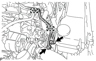
REMOVE EGR VALVE BRACKET
-
Remove the bolt, nut and EGR valve bracket from the electric EGR control valve assembly and intake manifold.
-
-
REMOVE NO. 2 EGR PIPE
-
Remove the bolt, 4 nuts and No. 2 EGR pipe from the electric EGR control valve assembly and intake manifold.
-
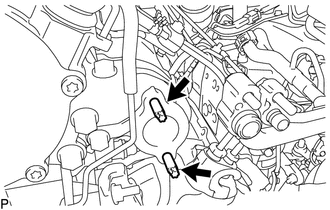
Remove the 2 gaskets.
-
-
REMOVE ELECTRIC EGR CONTROL VALVE ASSEMBLY
-
Detach the clamp and disconnect the connector from the common rail assembly.
-
Slide the clamp and disconnect the No. 9 water by-pass hose from the electric EGR control valve assembly.
-
Remove the 2 bolts and electric EGR control valve assembly.
-
Remove the gasket.
-
-
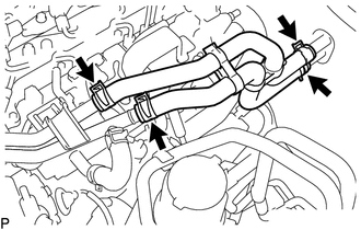
REMOVE NO. 3 WATER BY-PASS PIPE SUB-ASSEMBLY
-
Disconnect the No. 4 fuel hose from the No. 3 water by-pass pipe sub-assembly.
-
Slide the clamp and disconnect the No. 8 water by-pass hose from the No. 3 water by-pass pipe sub-assembly.
-
-
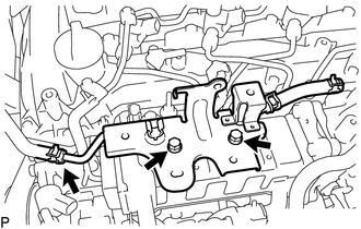
DISCONNECT NO. 4 WATER BY-PASS PIPE SUB-ASSEMBLY
-
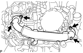
Slide the clamp and disconnect the No. 7 water by-pass hose from the No. 1 EGR cooler.
-
Slide the clamp and disconnect the water hose from the No. 2 EGR valve assembly.
-
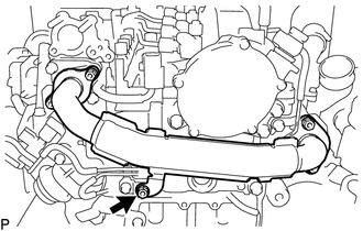
Remove the 2 bolts and disconnect the No. 4 water by-pass pipe sub-assembly from the intake manifold.
-
-
REMOVE NO. 1 EGR PIPE SUB-ASSEMBLY
-
Remove the bolt and disconnect the No. 1 EGR pipe sub-assembly from the vacuum transmitting pipe sub-assembly.
-
Remove the 4 nuts and the No. 1 EGR pipe sub-assembly from the exhaust manifold and EGR valve adapter.
-
Remove the 2 gaskets.
-
Using an E8 "TORX" socket wrench, remove the 2 stud bolts from the exhaust manifold.
-
-
REMOVE VACUUM CONTROL VALVE SET
-
REMOVE NO. 1 EGR COOLER WITH NO. 2 EGR VALVE ASSEMBLY
-
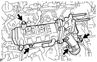
Remove the 4 bolts and No. 1 EGR cooler with No. 2 EGR valve assembly from the intake manifold.
-
-
REMOVE EGR VALVE ADAPTER
-
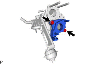
Remove the 2 bolts and EGR valve adapter from the No. 2 EGR valve assembly.
-
Remove the gasket.
-
-
REMOVE NO. 2 EGR VALVE ASSEMBLY
-
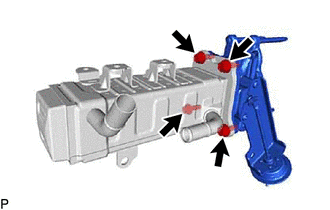
Remove the 4 bolts and No. 2 EGR valve assembly from the No. 1 EGR cooler.
-
Remove the gasket.
-
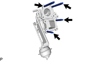
Using an E8 "TORX" socket wrench, remove the 4 stud bolts from the No. 2 EGR valve assembly.
-